


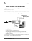

2 - Installation
14 Test Bed Receiver Subsystem Addendum – Rev 1
CONNECTING DATA COMMUNICATIONS EQUIPMENT
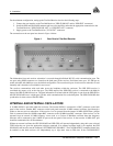
There are two serial ports on the back panel of the Test Bed Receiver; both are configured for RS-232 protocol. These
ports make it possible for external data communications equipment - such as a personal computer - to communicate with
the Test Bed Receiver. Each of these ports has a DE9P connector.
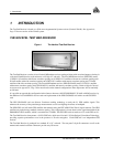
The GPS GLONASS and GPS GEO ports (see Figure 7) allow two-way communications. Each is configured as COM1
if you attempt to communicate directly with it. They are each connected to a GPSCard within the Test Bed Receiver unit.
Each of these ports can be addressed independently of the other.
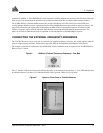
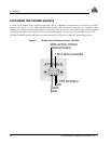
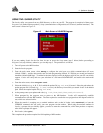
Figure 7 Pinout for GPS GLONASS and GPS GEO Ports - Test Bed
CONNECTING THE GPS ANTENNA
Selecting and installing an appropriate antenna system is crucial to the proper operation of the Test Bed Receiver.
The antenna connectors for both GPS and GLONASS are located on the back panel of the enclosure and are type TNC.
Antenna power is provided to the center pin of these connectors. The power is 5 V DC with a current up to 100 mA. The
power supply for the antenna originates from each receiver card in this enclosure and its status is reflected in the Antenna
Status bit of either receiver subsystem.
Keep these points in mind when installing the antenna system:
• Ideally, select an antenna location with a clear view of the sky to the horizon so that each satellite above the horizon
can be tracked without obstruction.
• Ensure that the antenna is mounted on a secure, stable structure capable of withstanding relevant environmental
loading forces (e.g. due to wind or ice).
Use high-quality coaxial cables to minimize signal attenuation. The gain of the LNA must be sufficient to compensate for
the cabling loss.
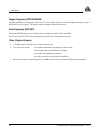
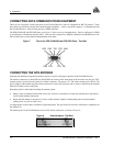
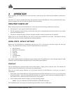
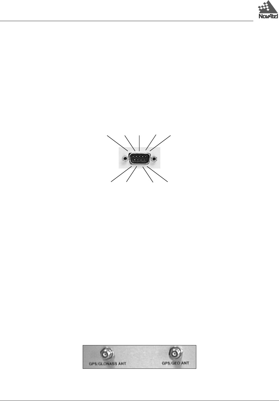
The antenna ports on the Test Bed Receiver have TNC female connectors, as shown in Figure 8.
Figure 8 Antenna Inputs - Test Bed
DSR RTS CTS NC
DCD RXD TXD DTR GND