


2 - Installation
12 Test Bed Receiver Subsystem Addendum – Rev 1
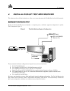
For the minimum configuration, setting up the Test Bed Receiver involves the following steps:
1. Connect the user interface to the Test Bed Receiver (“GPS GLONASS” and/or “GPS GEO” connectors)
2. Install the GPS and GLONASS antennas and low-noise amplifier, and make the appropriate connections to the
Test Bed Receiver (“GPS GLONASS ANT” or “GPS GEO ANT” connector)
3. Supply power to the Test Bed Receiver (“22-30 VDC” connector)
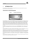
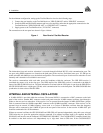
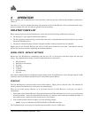
The connections on the rear panel are shown in Figure 4 below:
Figure 4 Rear Panel of Test Bed Receiver
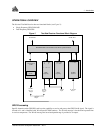
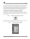
The information from each receiver subsection is accessed through individual RS–232 serial communication ports. The
two ports using DE9P connectors are located on the back panel of the receiver. Serial baud rates up to 115,200 bps are
usable selectable with 9600 bps set as the default configuration. The second serial port of each receiver subsection is used
internally and is therefore not available for user access.
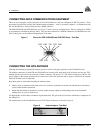
The receivers communicate with each other across the backplane within the enclosure. The GPS GEO receiver is
considered the master as far as the time goes. The 1PPS output of the GPS GEO receiver is connected to the Mark In
input of the GPS GLONASS receiver. The time information associated with the 1PPS pulse is sent from the GPS GEO to
the GPS GLONASS across a high-speed (TLink) serial communication line on the backplane. The GPS GLONASS then
synchronizes its time to that of the GPS GEO.
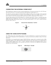
INTERNAL AND EXTERNAL OSCILLATORS
A 10 MHz OCXO is provided within the enclosure. The internal OCXO is connected to a BNC connector on the back
panel of the receiver. Another BNC connector on the back panel routes the 10 MHz external oscillator signal through a
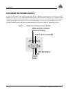
splitter to the two receiver subsections. If the receiver is to be operated from the internal 10 MHz OCXO then a jumper
cable is connected from the 10 MHz output BNC connector to the 10 MHz input BNC connector. If the receiver is to be
operated from an external 10 MHz frequency source such as a Cesium or Rubidium oscillator then that frequency
reference will be connected to the 10 MHz IN port on the rear panel of the receiver. In that case the 10 MHz OUT port
should be terminated with a 50
Ω terminator.
Without an external oscillator the GPS GLONASS and GPS GEO will operate independently using their own on-board
TCXO after they are given the appropriate software command. If an external oscillator input is not supplied, the GPS
GLONASS card must be sent the command “SETTIMESYNC DISABLE”. The CLOCKADJUST command should also
be enabled so that both receivers will independently try to align their time to GPS time. If the CLOCKADJUST