


2 - Installation
16 Test Bed Receiver Subsystem Addendum – Rev 1
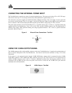
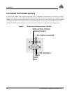
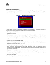
ACCESSING THE STROBE SIGNALS
A strobe port is located on the enclosure back panel. This is a diagnostic connector and is in the form of a DE9S
connector (see Figure 11). The 1PPS and Measurement pulse from both receiver subsystems are available on this
connector for verifying synchronization using an oscilloscope. These are the only strobe signals made available from the
two receiver subsystems. The specifications and electrical characteristics of these signals are described in Appendix B.
The GPS GLONASS and GPS GEO ports are each connected to a GPS receiver within the Test Bed Receiver unit.
Figure 11 Strobe 9-pin D-Connector Pinout - Test Bed
MSR GPS/GLONASS
MSR GPS/GEO
1 PPS GPS/GLONASS
1 PPS GPS/GEO
GND
GND
GND