


2 - Installation
Test Bed Receiver Subsystem Addendum – Rev 1 13
command is disabled, or if the EXTERNAL clock command is disabled, then the two receivers will drift away from each
other in time. The normal mode of operation is to use either the internal OCXO or a highly stable external oscillator.
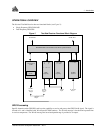
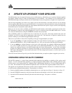
The 10 MHz OCXO is mounted within the enclosure on the Clock/Status card. This card has bi-colored LEDs that
visually indicate when the receiver is powered and also reflect whether the receiver has passed its power on self-test. The
lower LED will monitor the signal power of the internal 10 MHz OCXO. If it turns from green to off a failure of the
OCXO or its power supply would be indicated. Only the first, second and third LED from the bottom are used. The
others are only active when the enclosure is populated as a WAAS, MSAS, or EGNOS RIMS-C receiver.
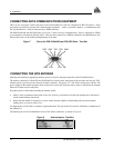
CONNECTING THE EXTERNAL FREQUENCY REFERENCE
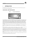
The Test Bed Receiver can be used with an external, user-supplied frequency reference; this would typically take the
form of a high-accuracy oscillator. Please refer to Appendix B for the recommended specifications of this device.
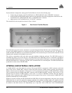
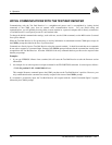
The frequency reference is connected to the 10 MHz BNC female connector on the rear panel of the Test Bed Receiver.
Refer to Figure 5 below.
Figure 5 10 MHz In (External Frequency Reference) - Test Bed
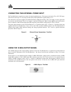
The 11
th
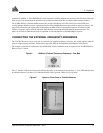
(bottom) LED on the front panel indicates the status of the internal clock reference. A clear LED indicates that
no internal reference is present. Green indicates that the clock is present. Refer to Figure 6 below.
Figure 6 Lights on Front Panel of Test Bed Receiver