


Reference Manual
00809-0100-4027, Rev AA
December 2005
4-3
Rosemount 4500
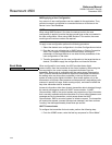
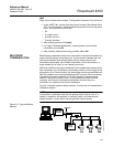
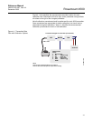
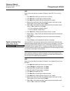
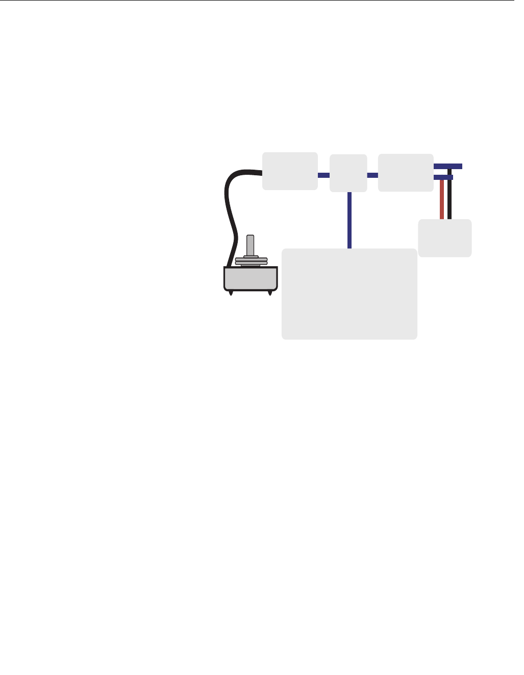
Figure 4-1 also identifies the approximate transmitter location for each
calibration task. Data flows from left to right, and a parameter change affects
all values to the right of the changed parameter.
Not all calibration procedures should be performed for each 4500 transmitter.
Some procedures are appropriate for bench calibration, but should not be
performed during field calibration. Table 4-1 identifies the recommended
calibration procedures for bench or field calibration.
Figure 4-1. Transmitter Data
Flow with Calibration Options
Transmitter Ranged 0 to 100 inH
2
O (0 to 0,25 bar)
NOTE
Value on PV line should equal the input pressure.
Value on AO line should equal the output device reading.
CALIBRATION
A/D MICRO D/A
20.00 mA
100 in. H
2
0
4500:LT-8793
Online
1 Device setup
2 PV 100.00 in.H
2
0
3 AO 20.00 mA
4 LRV 0.00 in.H
2
0
5 URV 100.00 in.H
2
0
SAVE