


Reference Manual
00809-0100-4027, Rev AA
December 2005
2-7
Rosemount 4500
Connect Wiring and
Power Up
Wiring for HART Protocol
NOTE
Use shielded twisted pairs to yield best results. To ensure proper
communication, use 24 AWG or larger wire, and do not exceed 5000 feet
(1 500 meters).
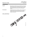
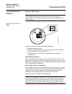
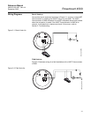
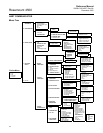
Figure 2-5. HART Terminal
Blocks
To make connections, perform the following procedure:
1. Remove the housing cover.
2. Connect the positive lead to the terminal marked (+) and the negative
lead to the terminal marked (pwr/comm –).
3. Tighten cord grip to avoid moisture accumulation in the terminal
compartment.
Signal Wiring Grounding
Do not run signal wiring in conduit or open trays with power wiring, or near
heavy electrical equipment. Ground the signal wiring at any one point on the
signal loop, or leave it ungrounded. The negative terminal of the power supply
is a recommended grounding point.
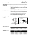
Power Supply 4–20 mA Transmitters
The dc power supply should provide power with less than two percent ripple.
Total resistance load is the sum of resistance from signal leads and the load
resistance of the controller, indicator, and related pieces. Note that the
resistance of intrinsic safety barriers, if used, must be included.
See load limitations in Section A: Reference Data.
NOTE
A minimum loop resistance of 250 ohms is required to communicate with a
HART Communicator. If a single power supply is used to power more than
one 4500 transmitter, the power supply used and circuitry common to the
transmitters should not have more than 20 ohms of impedance at 1200 Hz.
ALARM
SPAN
-LOOP
+LOOP
ZERO
SECURITY
-LOOP
+LOOP
4500_25_AA.EPS