


Reference Manual
00809-0100-4027, Rev AA
December 2005
2-5
Rosemount 4500
NOTE
Sensor burst pressure limits may be less than clamp pressure limits.
NOTE
Most transmitters are calibrated in the vertical position. Mounting the
transmitter in any other position will shift the zero point to the equivalent
amount of liquid head caused by the varied mounting position. To reset zero
point, refer to “Sensor Trim” on page 4-5.
Set Switches Security (Write Protect)
Changes can be prevented to the transmitter configuration data with the write
protection switches on the optional LCD or the switches on the optional LOI
board. Position the switch in the “ON” position to prevent change of
configuration data.
If the transmitter write protection switch is in the “ON” position, the transmitter
will not accept any “writes” to its memory. Configuration changes, such as
digital trim and reranging, cannot take place when the transmitter security is
on.
To reposition the switches, follow the procedure described below.
1. If the transmitter is installed, set the loop to manual and remove power.
2. Remove the electronics compartment cover.
3. Follow the procedure in Figure 2-4 to reposition the switches as desired
for the specific housing compartment.
4. Re-install the transmitter cover.
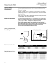
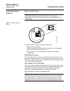
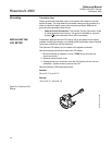
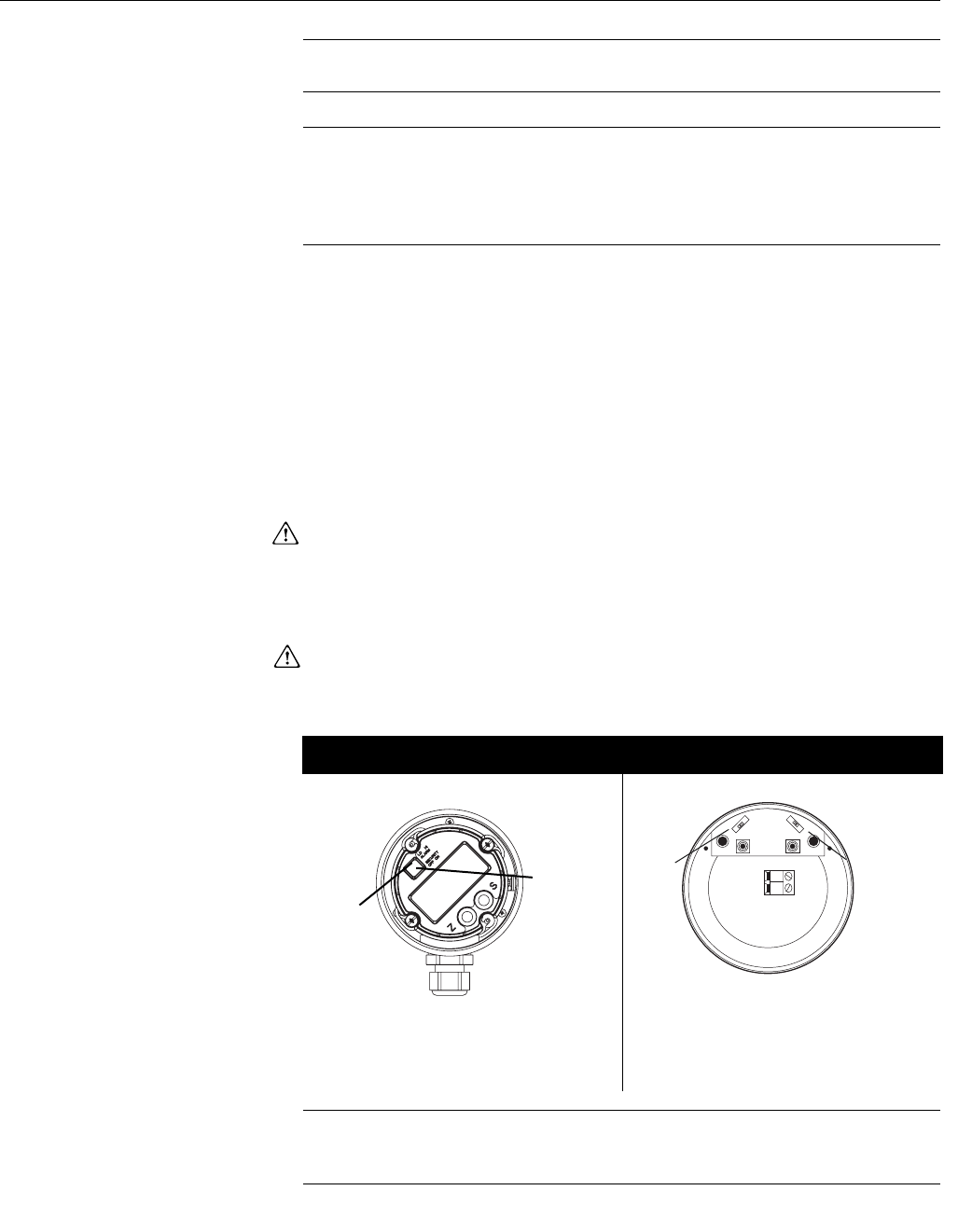
Figure 2-4. Switch configuration
NOTE
If alarm and security adjustments are not installed, the transmitter will operate
normally with the default condition alarm high and the security off.
LCD Switches LOI Switches
Slide the security and alarm
switches into the preferred position
by using a small screwdriver.
Slide the security and alarm
switches into the preferred position
by using a small screwdriver.
Alarm
Security
4500_26_AA
ALARM
SPAN
-LOOP
+LOOP
ZERO
SECURITY
Alarm
Security