


Reference Manual
00809-0100-4027, Rev AA
December 2005
Rosemount 4500
4-2
Table 4-1. Recommended
Calibration Tasks
NOTE:
The transmitter performs to specification only when completely and correctly
calibrated, including full sensor and analog output trim.
Calibration Overview Complete calibration of the 4500 pressure transmitter involves the following
tasks:
Configure the output parameters
• Set Process Variable Units (page 3-7)
• Set Output Type (page 3-8)
• Rerange (page 3-8)
• Set Damping (page 3-10)
Calibrate the sensor
• Full Trim (page 4-6)
• Zero Trim (page 4-6)
Calibrate the 4–20 mA output
• 4–20 mA Output Trim (page 4-8); or
• 4–20 mA Output Trim Using Other Scale (page 4-9)
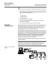
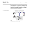
Figure 4-1 on page 4-3 illustrates 4500 transmitter data flow. Data flow can be
summarized in four major steps:
1. A change in pressure is measured by a change in the sensor output
(Sensor Signal).
2. The sensor signal is converted to a digital format that is understood by
the microprocessor (Analog-to-Digital Signal Conversion).
3. Corrections are performed in the microprocessor to obtain a digital
representation of the process input (Digital PV).
4. The Digital PV is converted to an analog value (Digital-to-Analog Signal
Conversion).
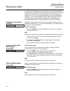
Transmitter Bench Calibration Tasks Field Calibration Tasks
4500_ G
4500_ A
1. Set output configuration parameters:
a. Set the range points.
b. Set the output units.
c. Set the output type.
d. Set the damping value.
2. Optional: Perform a full sensor trim if
equipment available (accurate pressure
source required), otherwise perform the
low trim value section of the full sensor
trim procedure.
3. Optional: Perform an analog output trim
(Accurate multimeter required)
1. Reconfigure parameters if necessary.
2. Perform low trim value section of the
full sensor trim procedure to correct for
mounting position effects.