


Reference Manual
00809-0100-4027, Rev AA
December 2005
Rosemount 4500
2-4
INSTALLATION
PROCEDURES
For dimensional drawing information refer to Appendix A: Reference Data.
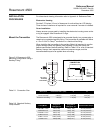
Electronics Housing
Provide 0.75 inches (19 mm) of clearance for units without an LCD display.
Three inches of clearance is required for cover removal if a meter is installed.
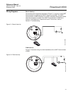
Cover Installation
Always ensure a proper seal by installing the electronics housing cover so the
o-ring is engaged. Use Rosemount O-rings.
Mount the Transmitter The Rosemount 4500 is designed to be mounted directly to a process pipe or
vessel using a standard sanitary fitting. The transmitter is available with either
a 1.5 or 2-inch Tri-Clamp
®
connection or a fractional line fitting.
When installing the transmitter to the sanitary fitting it is important to use the
proper sanitary clamp and gasket (user-supplied). Check the clamp and
gasket specifications before installing. Refer to Table 2-2 for a list of standard
sanitary clamps, their respective maximum pressure ranges, and the
recommended torque to be applied when mounting.
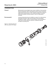
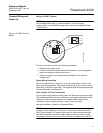
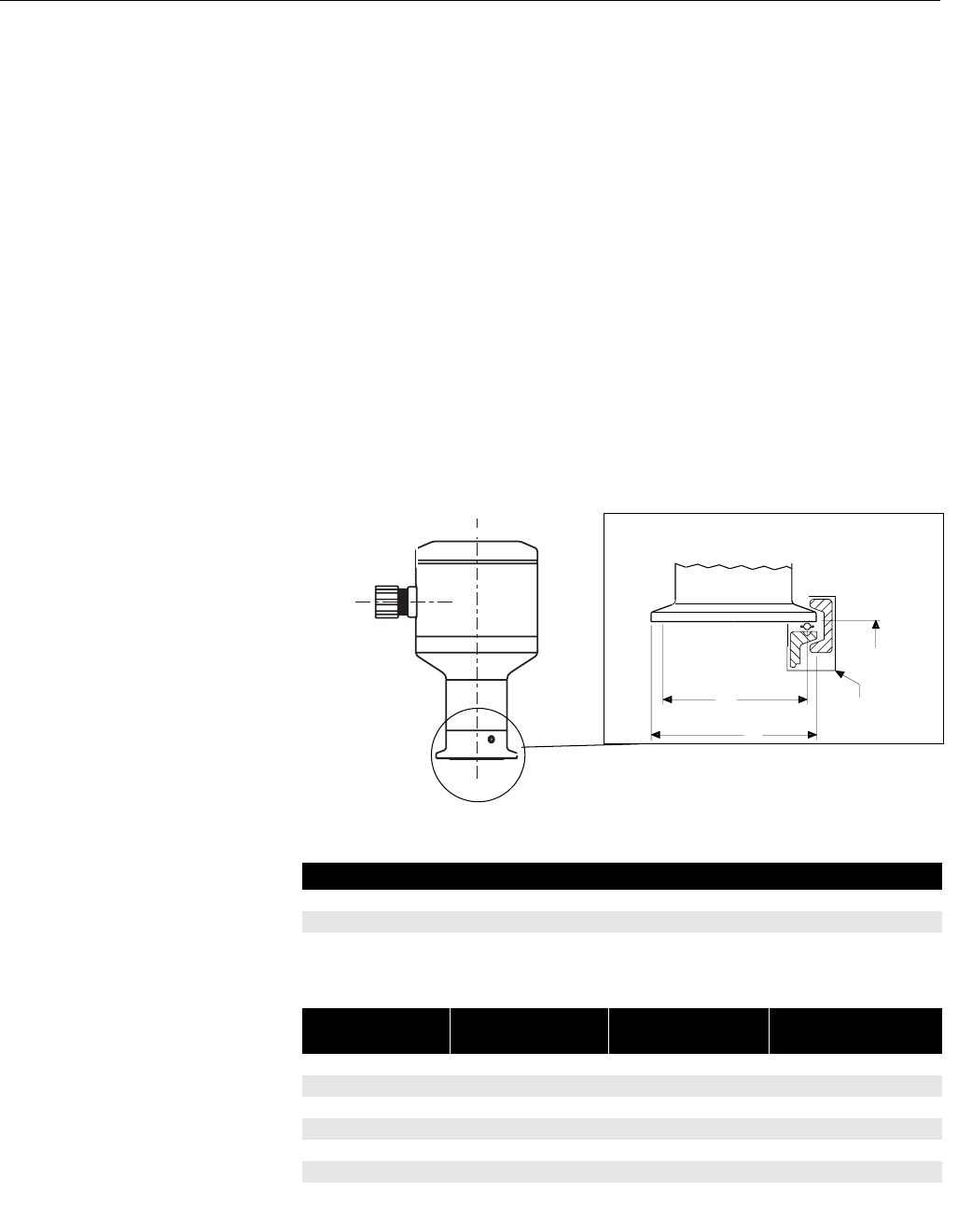
Figure 2-3. Rosemount 4500
Mounting Configuration Using a
Sanitary Fitting
Table 2-1. Connection Size
Table 2-2. Standard Sanitary
Clamp Models
1.5 or 2-in.
Tri-Clamp
Connection
User
Supplied
Gasket and
Clamp
B
A
DETAIL OF SANITARY
CONNECTION
4500_04_AA.EPS, 4500_24_AA.EPS
Description Connection Size in (mm) A B
1
1
/2 inch Tri-Clamp 1.50 (38) 1.99 (50) 1.71 (43)
2 inch Tri-Clamp 2.00 (51) 2.52 (64) 2.22 (56)
Fractional Line Fitting 1.50 (38) 1.99 (50) 1.50 (38)
Clamp Model
psi @ 70 °F
(kPa @ 21 °C)
psi @ 250 °F
(kPa @ 121 °C)
Recommended Torque
13 MHHM 1.5-inch 450 (3 103) 250 (1 724) 25 in-lb (2.8 N•m)
13 MHHM 2-inch 500 (3 448) 250 (1 724) 25 in-lb (2.8 N•m)
13 MHHS 1.5-inch 600 (4 138) 300 (2 069) 25 in-lb (2.8 N•m)
13 MHHS 2-inch 550 (3 793) 275 (1 896) 25 in-lb (2.8 N•m)
13 MHP 1.5-inch 1500 (10 345) 1200 (8 276) 20 ft-lb (27 N•m)
13 MHP 2-inch 1000 (6 896) 800 (5 517) 20 ft-lb (27 N•m)