ITW Dynatec c. 1999 Page 3 - 3
TPC-2 TIMER Manual #50-05 Revised 1/99
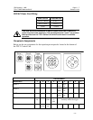
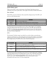
System Status Lights
There are four LED’s in the top right corner of the Display Panel that provide an
indication of the current system status. These lights are described in further detail below:
Drive 1 & Drive 2
These LED’s provide an indication of the current Drive Output activity. The LED’s will
be in one of the following states:
STATUS LIGHT MEANING
No Illumination: There is no Drive Output activity
GREEN: The Drive Output is functioning properly and is currently energized
RED: There is an electrical short or other fault in the Drive Output, Output Cable or Glue Valve
An electrical short circuit most likely exists if a Drive Status Light is red. Completely
inspect the Output Cables and Glue Valve for the cause. Turn OFF, then turn back ON
the TPC-2 Control Unit to clear the fault condition once the cause of the fault has been
located. See the TROUBLESHOOTING section of this manual for more information in
the event of a Drive Output fault.
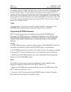
A.T.S.
The Automatic Tip Sealer output is provided for use with cold glue systems that may
employ tip sealing devices to prevent the glue from drying in the applicator nozzle during
periods of glue system inactivity. This LED provides an indication of the current A.T.S.
Drive Output activity. The LED will be in one of the following states:
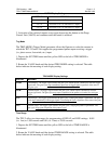
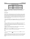
STATUS LIGHT MEANING
No Illumination: There is no A.T.S. Output activity. The A.T.S. Output automatically deactivates when the
TPC-2 does not receive a Trigger Input for 2.5 seconds.
GREEN: The A.T.S. Output is functioning properly and is currently energized. The A.T.S. Output
should activate immediately upon receipt of a Trigger Input.
RED: There is an electrical short or other fault in the A.T.S. Output circuitry, Output Cable or
Glue Valve
An electrical short circuit most likely exists if the A.T.S. Status Light is red. Completely
inspect the Output Cable and Tip Sealing Device for the cause. Turn OFF, then turn back
ON the TPC-2 Control Unit to clear the fault condition once the cause of the fault has
been located. See the TROUBLESHOOTING section of this manual for more
information in the event of an A.T.S. Drive Output fault.


