34 DC-190 Ultra Count Installation Manual
7.4 Global Setpoint Programming– Setpoints Not Tied to an Item Code
The DC-190 provides the flexibility to use the setpoint programming for parts counting applications that are
based on weight or quantity. SPEC 7 and SPEC 18 are used for configuring the setpoint type, latching, buzzer,
TTL outputs, and the number of setpoints.
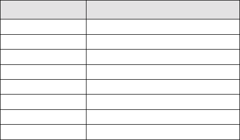
The eight-pin DIN connector designation for the setpoint configuration is shown in Table 7-3. See Section 10.3
on page 52 for connector pinout information.
The available setpoint types are quantity, weight, percent quantity, and percent weight. The following procedure
is the same for each type; however, the type of setpoint selected determines the values being entered. Table 7-1
details the values for each setpoint and the values they represent.
7.4.1 Procedure
The following steps present the procedure for setpoint programming by percent quantity, percent weight, upper
and lower quantity limit, and upper and lower weight limit.
1. Press the
MODE key to go into the programming mode. The MODE annunciator illuminates, the WEIGHT
display shows ProG, and the QUANTITY display shows C XX.
2. Press the
+ key to enter global setpoint values. The WEIGHT display shows Set 1, and the QUANTITY
display shows the value for Setpoint 1.
3. Enter the setpoint value using numeric keys.
4. Press the
+ key to store the value and move to the next setpoint.
5. Press the
MODE key to exit the programming mode and return to the weighing mode.
NOTES:
• The DC-190 can program up to six setpoints by repeating Steps 2 through 4. SPEC 18, bits 0, 1, and 2
(Number of Setpoints) determine the number of setpoints used. The six setpoints are TTL output for
quantity or weight, but not percentage quantity or percentage weight. These six values may be
programmed 1 through 6 (low-to-high) or 1 to 6 (high-to-low).
• If you recall an item code, those values stored with the item are used. Item setpoints take priority.
Pin Number Setpoint Configuration
1 SP-1
2 SP-2
3 SP-3
4 SP-4
5 SP-5
6 SP-6
7 +5 Vdc (external power supply)
8 GND
Table 7-3. Pin Out for Setpoint Configuration


