


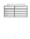
9
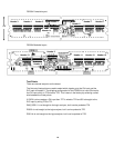
Signal Assignments on Probe Pods
The overlap in the bit ranges (for DQxx) signals between pods occurs because the bits
are assigned to pods in the order that they appear physically on the DDR2 DIMM
connector, which is not strictly in logical bit order. This allows the Probe layout to better
match stub lengths among all DQxx signals.
See the Appendix for a detailed list of how Logic Analyzer Channels are mapped to
signals and DDR2 pins.
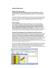
Signal Threshold Voltage Settings
The standard voltage threshold for the logic analyzer pods is defined as 900mV. This is
based on the SSTL2-1.8V signaling used by the DDR2 DIMM bus. The configuration
files provided with this product set-up the threshold voltages for both the Data and
Command pods to 900mV. Design differences between target platforms or overvoltage
settings may require adjustment of the logic analyzers threshold for optimal signal
capture. The use of Eye Scan can be very helpful in determining where to set these
thresholds.
NOTE: The optimal settings may need to be defined either through trial and error
or by using Eye Scan. Accurate data capture is very dependent on optimizing
these settings and changes of as little as 50mV may have a significant effect.
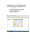
Connecting the DDR2 Probe to the Logic Analyzer
The FS2334 DDR2 Probe requires up to 7 logic analyzer cards depending on whether
state (Read and Write - quadruple sampled), state (Read or Write - dual sampled), or
timing measurements are desired. See Timing and State configuration information
below.
At this time the user may find it easier to connect the logic analyzer cables to the probe
before inserting the probe into the target system. The FS2334 probe has fourteen 90 pin
pod connections which mate directly to Agilent Logic analyzer cards. Adapter cables are
not required. Once a configuration file is loaded refer to the General Purpose Probe
feature in the Agilent 1690x Overview tab for cable connections.