


19
State Analysis Operation – Read and Write at 667MT/s or slower
State mode capture is performed by using both edges of CK0. This double probing of
each signal is handled internally by the Agilent Logic Analyzer using the Dual Sample
mode feature. State analysis within these parameters only requires dual sampling of the
Data signals, which can be done with 4 cards in one frame. The four cards used for
state analysis must be configured as one logic analyzer machine. You may also place
the cards in slots other than described here, but must then adjust the pod connection
tables and configuration file loading instructions accordingly. The configuration file is set
up with the Master in slot D, expanders in C, E, and F.
The analyzer sample position of the channel capturing data is set via a calibration
procedure (described in this document) to the optimum value. The DDR
Command/Address bus is also sampled (along with the Data bus) on both edges of
CK0. This does not reduce triggering capability but does require additional care when
setting up triggers because the command/address bus is not valid on the falling edge of
CK0.
The Auto Sample Position Set-up function can be a more accurate means to set the
sampling position for each bit used in the State analysis, but this requires using known,
continuous data patterns of exclusive Reads and then exclusive Writes.
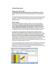
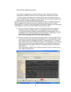
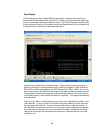
The logic analyzer’s TimingZoom traces can be used to set the sampling positions for
the labels as described in the following sections. Note: The label names are different
depending on whether you are doing Read and Write <= 667MT/s (FS1117) or doing
Read or Write at 800 MT/s (FS1136).
State Analysis Operation – Read or Write at 800MT/s
This mode of State Analysis permits just the use of 4 cards and one logic analyzer
frame. There are 2 different configuration files provided, on for Read only and one for
Write only State analysis. These configuration files use the FS1136 Protocol Decoder
and difference between the 2 is there pre-defined sampling positions are set for one
type of data burst or the other. The State clock operates on only the rising edge of the
clock and each data signal is sampled twice.
Please note that the Protocol decoder listing will show invalid data for the type of burst
that the sampling positions are not defined for.
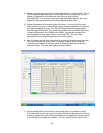
Setting the sampling positions is done in the same manner as for the 7 card, 800MT/s
configuration, the only difference being fewer labels to set sampling positions for.