


26
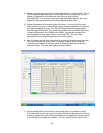
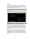
State Display
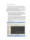
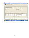
The following figure shows a typical DDR2 screen display. Because the analyzer may
sample data on both edges of the clock (FS1117) there are going to be some states that
have no commands or data associated with them. The Protocol Decoder contains a filter
that will allow post filtering of any states included Not Selected state, which is defined as
a state that has no command or data associated with it.
Symbols were created for the Command label. These symbols make searching for a
particular command in a listing easier as well as setting up triggers. These decode the
RAS, CAS, and WE lines to display the DDR Command as “Read”, “Write”, etc., so you
don’t have to refer to the DDR chip data sheet to see what command is being executed.
These decoded values are displayed by setting the display base (in the listing window)
or the label property (in the waveform window) to “Symbols”. The display base defaults
to hexadecimal.
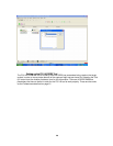
Filtering on the 169xx is configured by the user there are no predetermined filters in the
169xx decoder. To set up a filter in the 169xx environment select tools from the menu
bar, then select filter/colorize. You can choose to filter before or after the decoder. If
you filter before the decoder, use caution to not filter any labels needed by the decoder.
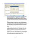
If you filter after the decoder you can use the label “filter tags” created by the decoder,
change hex to symbols and use symbols to remove any command that the user does
not want to see.