


10
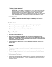
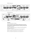
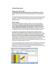
FS2334 Frontside layout
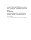
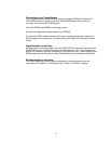
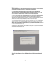
FS2334 Backside layout
Test Points
There are several test point on the board.
The first set of test points are used to select which signals go to the Clk input and the
D15 input of Header 2. The shipping configuration for the FS2334 is to have S0 wired to
the Clk input, which is TP3 wired to TP2. This is done in the factory by soldering a short
wire between the 2 test points.
If CKE0 is to be used as a Clk input then TP7 is wired to TP2 and S0 is brought to the
D15 input by wiring TP3 to TP1.
DM2_DQS11 is not brought to the logic analyzer, but it can be probed at TP4
DQS5n is not brought to the logic analyzer, but it can be probed at TP5
DQS14n is not brought to the logic analyzer, but it can be probed at TP6
Heade
r
3 Header 4 Heade
r
5
Heade
r
14
Heade
r
1
Heade
r
6
Heade
r
7 Heade
r
8
Heade
r
13
Heade
r
9
Heade
r
2
Heade
r
11 Heade
r
10 Heade
r
12
TP 5
TP 6 TP 4
TP 1,2,3,7
1.25”