


22
4) Repeat this procedure using the next rising edge of Write – Command:CK2_TZ and
the corresponding data burst cycle (it will be right next to the burst cycle you just
looked at). Measure the time difference from the rising edge of Write –
Command:CK2_TZ to both the center of the data eyes associated with the rising
edge of the Data strobe and then the falling edge of the Data strobe.
5) Repeat this procedure for several cycles of the burst. You may do this for other
bursts as well if you wish to cover different types of data burst patterns and account
for possible edge jitter sources. You may also find that the timing varies slightly
from Data byte to Data byte. This can be due to differences in the DIMM layout and
individual differences in the DRAMs on the DIMM. Compute the average of the
times between the rising edge of Write – Command:CK2_TZ for each byte
associated with the rising and separately for the falling labels.
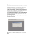
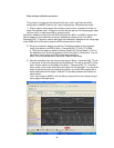
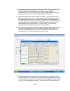
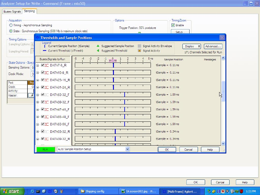
6) Now it is time to use this delay information to set the logic analyzer sample position.
From the “Sampling” tab of the “Write - Command” analyzer window click the
”Thresholds and Sampling Positions” button to bring up the sample positions for
Write data labels. (The write data labels are shown below).
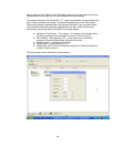
7) Set the sample position to be equal to the average time you computed in step 5.
The easiest way to do this is to point to the blue vertical sample position bar with the
mouse and press and hold the left mouse button while dragging the blue bars as far
to the left side of the display as possible. This will cause all the blue bars for that