


18
State Analysis
Overview
There are several choices for State mode analysis using the FS2334 DDR2 probe
depending on the speed of the data bus being probed and the number of logic analyzer
cards available to the user. At data speeds of up to 667MT/s the logic analyzer can be
triggered on BOTH edges of the clock signal used for State analysis (state clock), at a
data speed of 800MT/s ONLY the rising edge of the state clock can be used.
Because the sampling point for a data signal is at a different position relative to the state
clock edges during a Read data burst than during a Write data burst you need 2
sampling points established for each data signal, which allows the analyzer to sample a
data signal twice at speeds up to 667MT/s. When you only have sampling on the rising
edge of the state clock (800MT/s) you need to sample each data signal four times
because you need to account for both the 2 data states per clock and both Reads and
Writes. This is all done by the logic analyzer cards, which drives the cards requirements.
If a user is willing to sample ONLY Read OR Write bursts at 800MT/s, then you reduce
your sampling requirements by ½.
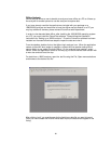
FuturePlus has provided configuration files and a set-up procedure that anticipates
these different scenarios and has described them in the following pages. Please note
that these are for DIMMs without ECC because the addition of the DQ64-72 bits would
force the user to add another card in all the configurations. These bits are available
(refer to the Appendix) if the user wants to modify the existing configuration files and/or
add an additional logic analysis card.
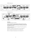
State Analysis Operation – Read and Writes above 667MT/s
State mode capture of Reads and Writes at data rates above 667MT/s requires
quadruple sampling of the Data bits and is performed by using the rising edge of CK0.
This requires 7 cards, which means that for every Data bit there are 4 labels (or
sampling positions), Write Data rising and falling, and Read Data rising and falling. The
analyzer sample position of each channel is set as described later in this manual. The
DDR Command/Address bus is also sampled (along with the data bus) on the rising
edge of CK0.
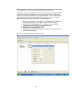
The 7 cards are configured as 2 logic analyzer machines (Write/Command and Read) in
2 separate frames. CK signals are provided to both machines as well as MRASn and
RASn, which are 2 copies of the same signal from each logic analyzer machine that can
be used as a reference signal for intermodule skew adjustment.
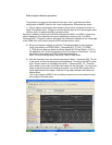
The configurations are set-up with 4 cards melded together in Frame # 1 in slots C, D
(master), E and F. Frame #2 has 3 cards melded together in slots A, B (master) and C.
The frames need to be connected through the Intermodule cable and share a network
connection. More detailed information is available within the Help documentation on
your Agilent Logic analysis frame under “Multiframe operation”.
If you are using the special configurations for 32 bits of Read and Write Data decode
only, then a 4 card configuration in one frame is all that is required.