


7
Step 1 Connect the monitor to the processor.
Step 2 Connect the male end of the A&D-supplied RS-232C communication cable to the
processor.
Step 3 Connect the female end of the A&D-supplied RS-232C communication cable to the
computer.
Step 4 The display on the processor will show “0-----”. If the processor does not have a
display, the LED should be green. If the LED is not green or the “0-----” does not
appear, see “3-2 Communication Errors”. If the processor shows “0-----”, go to step
5. If the processor has a green light, go to step 6.
Note: If possible, keep the cable connected to the computer unless the port is needed
for other functions.
Step 5 Press the ENTER key on the processor keypad. A series of 6 dashes “------” will
appear on the processor screen.
Step 6 Run the software.
Step 7 Confirm that the correct serial port is set. For details, see “2-9-4-2 Serial Port”.
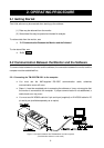
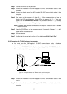
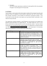
2-2-2 Connecting the TM-2430 series to the computer
♦ You must use the A&D-supplied RS-232C communication cable, otherwise
communication errors will occur.
♦ You must use AX-KO1502 cable for 9 pin serial port (supplied) or AX-KO1503 cable for
25 pin serial port (available separately as an option).
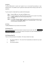
Figure 2 : Connection between the TM-2430 series and the computer
(The illustration above is not to scale.)
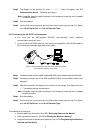
Step 1 Connect the male end of the A&D-supplied RS-232C communication cable to the
monitor.
Step 2 Connect the female end of the A&D-supplied RS-232C communication cable to the
computer.