Triggering
Reference
When READY is lighted, it means the digitizing oscilloscope can accept a
valid trigger event, and the digitizing oscilloscope is waiting for that event
to occur.
When ARM is lighted, it means the trigger circuitry is filling the pretrigger
portion of the waveform record.
When both TRIG’D and READY are lighted, it means the digitizing oscil-
loscope has recognized a valid main trigger and is waiting for a delayed
trigger. When the digitizing oscilloscope recognizes a delayed trigger, it
will fill in the posttrigger portion of the delayed waveform.
When ARM, TRIG’D, and READY are all off, the digitizer is stopped.
When ARM, TRIG’D, and READY are all lighted, FastFrame is in effect.
No trigger status monitoring is taking place.
Trigger Display Readout
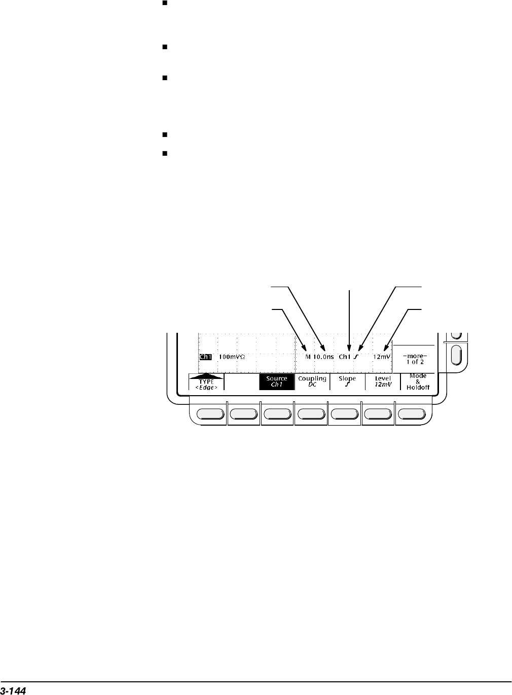
At the bottom of the display, the Trigger readout shows some of the key
trigger parameters (Figure 3-77). The readouts are different for edge, logic
and pulse triggers.
Main Trigger Slope =
Rising Edge
Main Time Base
Main Time Base Time/Div
Main Trigger
Source = Ch 1
Main Trigger
Level
Figure 3-77: Example Trigger Readouts
The record view at the top of the display shows the location of the trigger
signal in the waveform record and with respect to the display (see Fig-
ure 3-78).
Trigger Position and Level Indicators
In addition to the numerical readouts of trigger level, there are also graphic
indicators of trigger position and level which you can optionally display. These
indicators are the trigger point indicator, the long trigger level bar, and the
short trigger level bar. Figure 3-78 shows the trigger point indicator and
short-style trigger level bar.


