


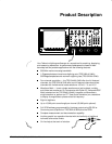

Start Up
Getting Started
4. Check that you have the proper electrical connections. The digitizing
oscilloscope requires 90 to 250 VAC
RMS
, continuous range, 47 Hz to
63 Hz, and may require up to 300 W.
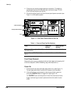
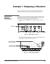
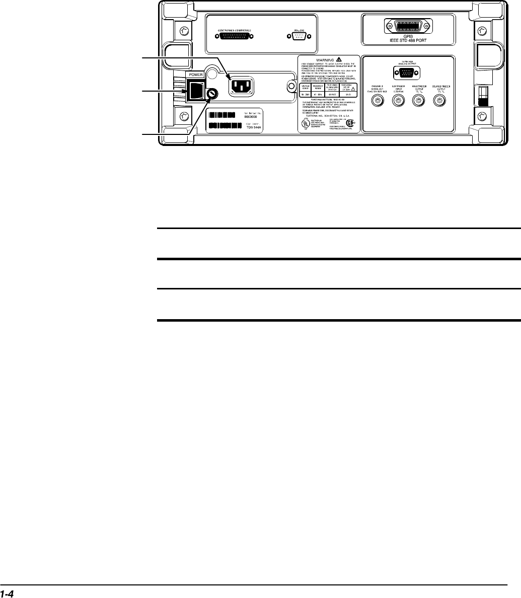
5. Connect the proper power cord from the rear-panel power connector (see
Figure 1-1) to the power system.
Power Connector
Principal Power Switch
Fuse
Figure 1-1: Rear Panel Controls Used in Start Up
Table 1-1: Fuse and Fuse Cap Part Numbers
Fuse
Fuse Part
Number
Fuse Cap Part
Number
.25 inch × 1.25 inch (UL 198.6, 3AG):
6 A FAST, 250 V.
159–0013–00 200–2264–00
5 mm × 20 mm (IEC 127): 5 A (T),
250 V.
159–0210–00 200–2265–00
Front Cover Removal
Remove the front cover by grasping its left and right edges and snapping it off
of the front subpanel. (When reinstalling, align and snap back on.)
Power On
1. Check that the rear-panel principal power switch is on (see Figure 1-1).
The principal power switch controls all AC power to the instrument.
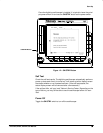
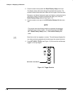
2. If the oscilloscope is not powered on (the screen is blank), push the
front-panel ON/STBY button to toggle it on (see Figure 1-2).
The ON/STBY button controls power to most of the instrument circuits.
Power continues to go to certain parts even when this switch is set to
STBY.