


29
ADJUSTING THE EXTENDED
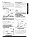
ACTIVE ANTI-TIPPERS (FIGURE 1)
NOTE: Extended Active Anti-tippers are standard when
chair is equipped with vent tray.
WARNING
Power chairs equipped with ventila-
tor tray MUST have extended active
anti-tippers installed, otherwise, injury
or damage may occur.
Power chairs that are NOT equipped
with optional ventilator tray MUST
have either the standard anti-tippers
or the the optional extended active
anti-tippers installed, otherwise, injury
or damage may occur. See DETAIL "A" in
FIGURE 1.
NOTE: The recommended height requirement for
the anti-tippers, which is factory preset, is 1/4-inch
off of the ground.
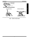
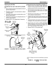
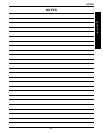
FIGURE 1 - ADJUSTING THE EXTENDED
ACTIVE ANTI-TIPPERS
Ground/Floor
1/4-inch Block
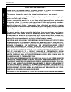
Extended Anti-tip
Assembly
Locknut B
Locknut A
Locknut C
Bearings
Dust Cover
is placed here
1. Loosen locknut C, B, and A.
2. Lift anti-tipper place 1/4-inch block underneath
wheel.
3. Tighten locknut A upward against bearing.
4. Tighten locknut B upward against locknut A.
5. Tighten locknut C downward against bearing in-
side anti-tip assembly.
6. Remove 1/4-inch block.
7. Repeat procedure for remaining anti-tip assem-
bly.
8. Install dust cover on each anti-tip assembly.
This Procedure Includes the Following:
Using the Extended Active Anti-Tippers
PROCEDURE 11ANTI-TIPPERS
A
N
T
I
-
T
I
P
P
E
R
S
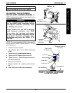
DETAIL "A"
Standard
Anti-tippers
Extended
Active
Anti-tippers