


25
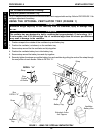
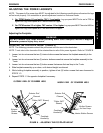
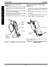
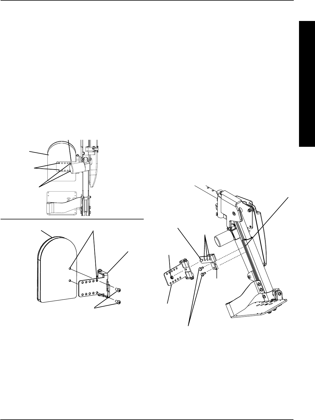
ADJUSTING THE CALF PAD DEPTH (FIGURE 12).
1. Loosen, but do not remove, depth adjustment
bracket mounting screws and slide calf pad as-
sembly up and out of the mounting channel.
2. Remove the flat head socket screw, and locking
hex nut that secure the calf bracket to the depth
adjustment bracket.
3. Reposition the calf bracket on the depth adjust-
ment bracket to desired position
4. Install the flat head socket screw through the calf
bracket, depth adjustment bracket and locking hex
nut.
5. Tighten locking hex nut to screw until snug. Do not
overtighten nut or calf pad will not pivot properly.
6. Align the two (2) T-nuts on depth adjustment
bracket assembly with channel on legrest. Slide
calf pad assembly to desired height. Tighten the
two (2) hex mounting screws securely.
7. Repeat STEPS 1-6 for opposite side.
FIGURE 12 - ADJUSTING THE CALF PAD
DEPTH
Calf
Bracket
Locking
Hex Nut
Depth
Adjustment
Bracket
Depth
Adjustment
Holes
NOTE: Calf pad not shown for clarification purposes
only.
Depth Adjustment
Bracket Hex Head
Screws
Flat
Head
Mounting
Screw
Mounting
Channel
Adjusting the Calf Pad
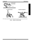
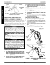
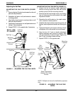
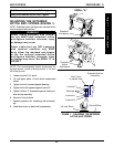
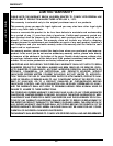
ADJUSTING THE CALF PAD WIDTH (FIGURE
11).
1. Remove the two (2) button head screws from the calf
pad and calf pad bracket.
2. Reposition calf pad to calf pad bracket to desired
mounting position.
3. Align button head screws to mounting holes on calf
pad and calf pad bracket.
4. Install button head screws into calf pad bracket and
calf pad. Securely tighten.
5. Repeat STEPS 1-4 for opposite side, if necessary.
FIGURE 11 - ADJUSTING THE CALF PAD WIDTH
Button Head
Screws
Calf Pad
Bracket
Mounting
Holes
Calf Pad
Button Head Screws
Calf Pad
Bracket
Mounting Holes
Calf Pad
BACK VIEW
OF LEGREST
RIGGINGS
R
I
G
G
I
N
G
S
PROCEDURE 8