


24
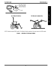
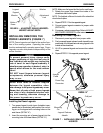
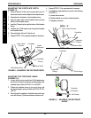
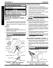
ADJUSTING THE FOOTPLATE DEPTH
(FIGURE 9).
1. Remove the two (2) flat head screws and the two (2)
barrel nuts that secure the footplate to the footplate clamp.
2. Reposition the footplate on the footplate clamp.
3. Align the depth holes on the footplate to the mounting
holes on the footplate clamp.
4. Insert the (2) barrel nuts through the bottom of the footplate
clamp.
5. Install the two (2) flat head screws through the footplate
and footplate clamp.
6. Securely tighten with two (2) barrel nuts.
7. Repeat STEPS 1-6 for opposite footplate if necessary.
Barrel Nuts
Footplate
Clamp
Depth
Adjustment
Holes
FIGURE 9- ADJUSTING THE FOOTPLATE DEPTH
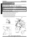
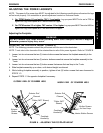
Flush Head
Screws
Footplate
Mounting Holes
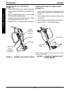
Set Screw
Direction
of Rotation
Footplate
Clamp
Pivot Hinge
Footplate
Barrel Nuts
Flush Head Screws
Footplate
Footplate
Clamp
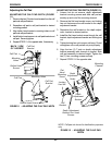
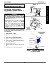
FIGURE 10 - ADJUSTING THE FOOTPLATE
ANGLE
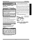
4. Repeat STEPS 1-3 for opposite side if necessary.
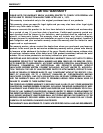
5. For additional angle adjustment, perform the following
(FIGURE 11):
A. Loosen the set screw.
B. Rotate footplate up or down to desired position.
C. Retighten set screw.
DETAIL “A”
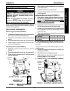
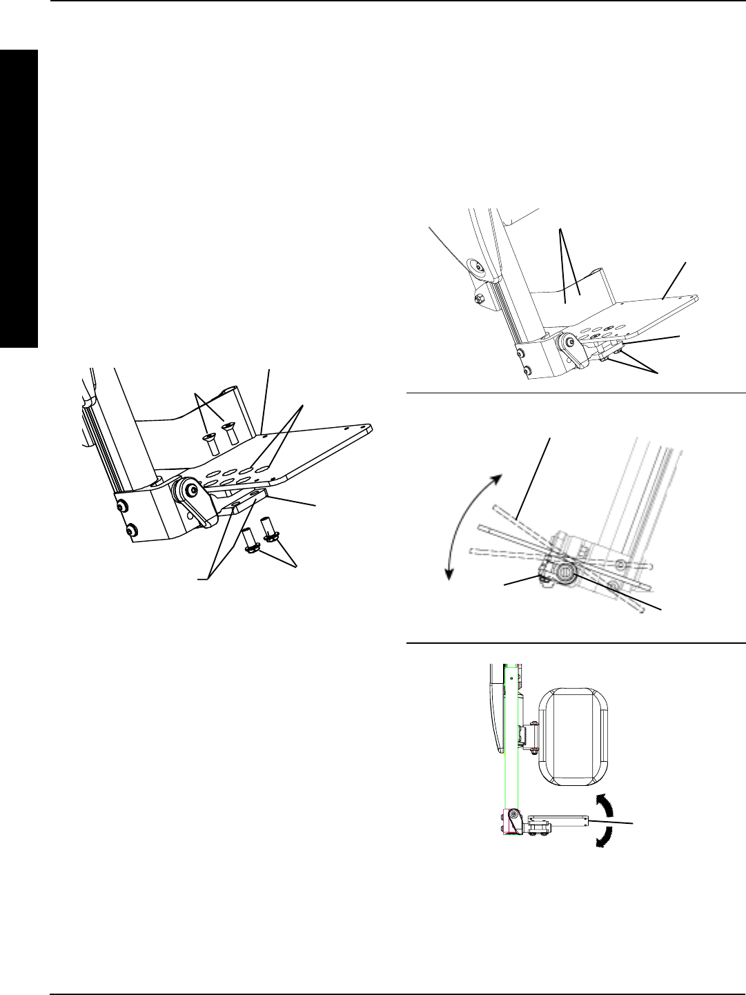
DETAIL “B”
PROCEDURE 8 RIGGINGS
R
I
G
G
I
N
G
S
ADJUSTING THE FOOTPLATE ANGLE
(FIGURES 10).
1. Loosen, but do not remove the two (2) flat head screws
and the two (2) barrel nuts that secure the footplate to the
footplate clamp. Refer to DETAIL A in FIGURE 7.
2. Rotate the footplate clamp on the pivot hinge until
the desired angle is achieved. Refer to DETAIL B FIG-
URE 10.
3. Securely tighten footplate to footplate clamp and hinge
pivot with the two (2) flat head screws and barrel nuts.