


23
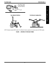
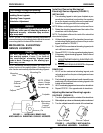
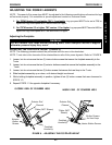
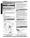
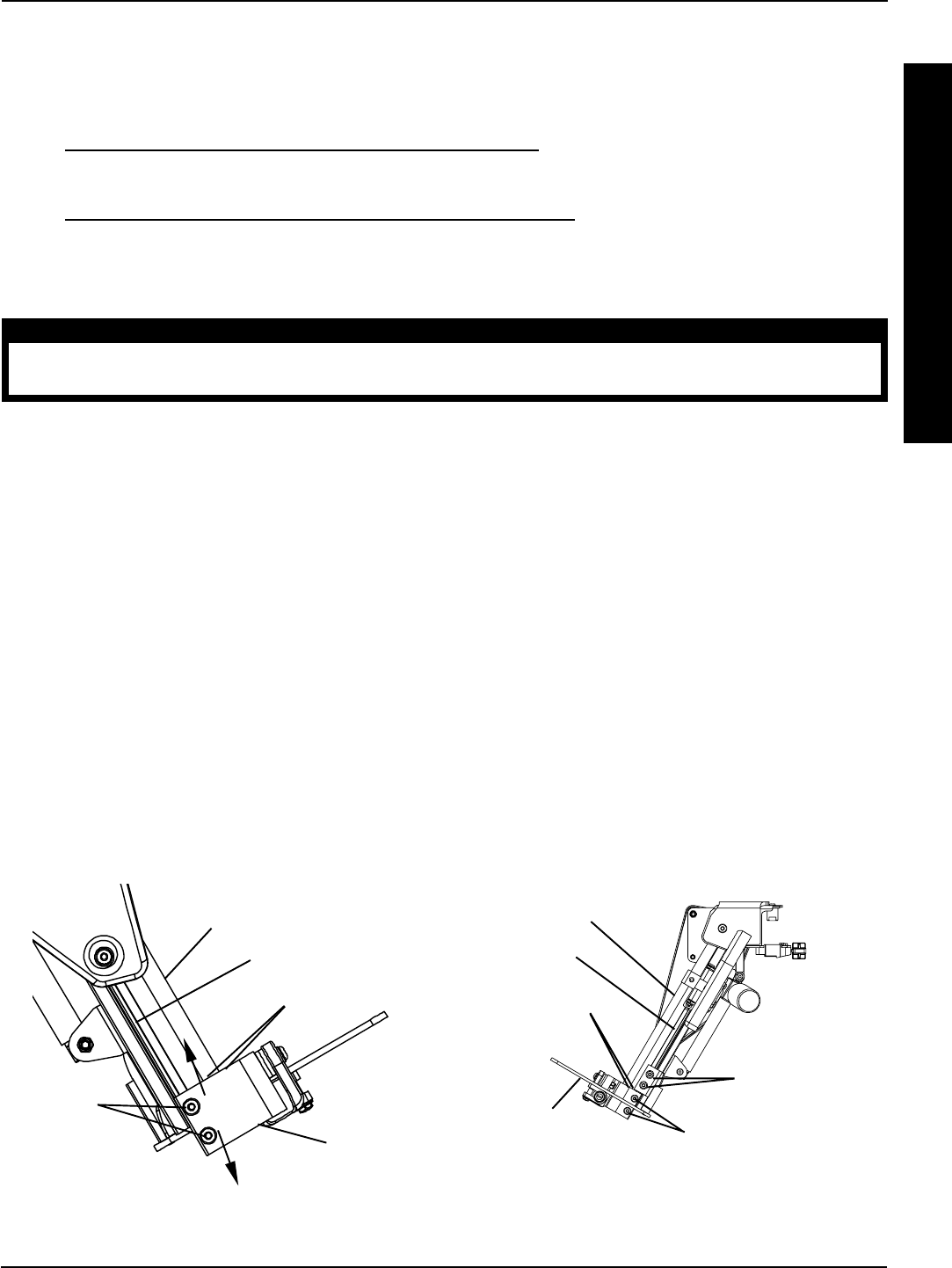
FIGURE 8 - ADJUSTING THE FOOTPLATE HEIGHT
OUTSIDE VIEW OF POWERED LEGS
Exterior Rail
Channel
T-Nuts (NOT Shown)
Footplate
Assembly
Exterior
Button
Screws
Exterior Rail
Channel
T-Nuts (NOT
Shown)
Footplate
Assembly
Button Screws
for Heel Loop
INSIDE VIEW OF POWERED LEGS
Interior Button Screws
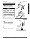
ADJUSTING THE POWER LEGRESTS
NOTE: The speed of the power legs MUST be adjusted to the following specifications otherwise the legs
will not work properly. For assistance in speed adjustment contact an Invacare Dealer.
A.
For TRCM Version 2.2 and earlier, TAC 1.1 and earlier: Leg up speed MUST to be set at 70% or
higher and Leg Down speed MUST be set at 50% or higher.
B. For TRCM version 2.3 or higher, TAC version 1.11 or higher: Leg up speed MUST be set at 40% or
higher and Leg Down speed MUST be seat at 35% or higher.
Adjusting the Footplate
WARNING
DO NOT remove heel loops without providing some other adequate means of support,
otherwise personal injury may occur.
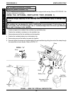
ADJUSTING THE FOOTPLATE HEIGHT (FIGURE 8).
NOTE: The following procedure should be performed with the user in the wheelchair.
NOTE: T-nuts ride in the channels of the exterior/interior rails of the power legrests. Refer to FIGURE 8.
1. Loosen, but do not remove the two (2) interior button screws that secure the footplate assembly to the
T-nuts.
2. Loosen, but do not remove the two (2) exterior button screws that secure the footplate assembly to the
T-nuts.
3. Loosen, but do not remove the two (2) button screws that secure the heel loop to the T-nuts.
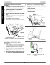
4. Slide footplate assembly up or down, until desired height is achieved.
5. While holding footplate assembly in position, tighten all six (6) button screws that were loosened in
STEPS 1-3.
6. Repeat STEPS 1-3 for opposite footplate if necessary.
RIGGINGS
R
I
G
G
I
N
G
S
PROCEDURE 8