


21
SPEED/HEIGHT.
NOTE: Mechanical Elevating Legrest speed and height
cannot be adjusted independently of the recline function
of the wheelchair. If the mechanical elevating legrests are
not operating as desired, have the wheelchair serviced
by an Invacare dealer or technician.
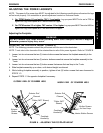
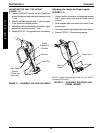
Adjusting Genius Legrests
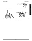
FOOTPLATE HEIGHT (FIGURE 4).
1. Note the angle of the footplate in relation to the legrest
as shown in FIGURE 1.
2. Loosen, but do not remove the three (3) hex bolts and
locknuts that secure the footplate to the legrest.
3. Adjust the fooplate to the desired height.
4. Line up the footplate to the angle noted in STEP 1.
5. While holding the footplate, tighten the three (3) hex
bolts and locknuts securely.
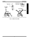
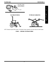
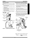
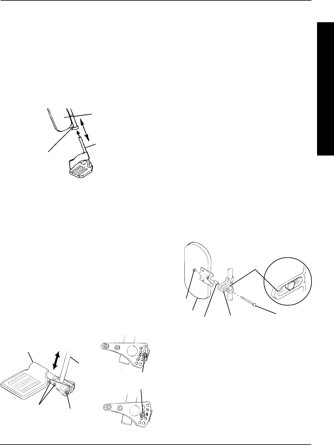
FIGURE 3 - ADJUSTING MECHANICAL
ELEVATING LEGRESTS - FOOTPLATE HEIGHT
RIGGINGS
R
I
G
G
I
N
G
S
PROCEDURE 8
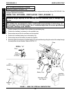
FIGURE 4 - ADJUSTING GENIUS LEGRESTS -
FOOTPLATE HEIGHT/ANGLE
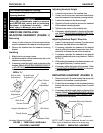
LEGREST HEIGHT (FIGURE 6).
1. Remove the button screw that secures the adjust-
ment link and two (2) washers to the legrest support.
2. Move adjustment link to one (1) of three (3) positions.
3. Line up the two (2) washers and adjustment link with
the mounting hole in the legrest support.
4. Install the button screw and tighten securely.
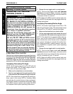
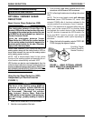
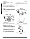
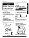
FIGURE 5 - ADJUSTING GENIUS LEGRESTS -
CALFPAD HEIGHT/DEPTH
Hex Bolts and
Locknuts
Footplate
Legrest
Rear Hex Bolt
and Locknut
Rear Hex Bolt
and Locknut
Hex Bolt
Calfpad
Spacer
Locknut
Adjustment
Bracket
Adjustment
Bracket
Channel
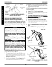
FOOTPLATE HEIGHT (FIGURE 3).
NOTE: The following procedure should be performed with
the user in the wheelchair.
1. Loosen, but do not remove the bolt and locknut that
secure the lower legrest assembly to the upper legrest
assembly.
2. Move the lower legrest assembly to the desired posi-
tion for the user.
3. While holding the lower legrest in position, tighten the
bolt and locknut securely.
4. Repeat STEPS 1-4 for opposite legrest if necessary.
FOOTPLATE ANGLE (FIGURE 4).
1. Note the angle of the footplate in relation to the legrest
as shown in FIGURE 1.
2. Remove the rear hex bolt and locknut that secure the
footplate to the legrest.
3. Move the footplate to the desired angle.
4. Install the hex bolt through the mounting holes that corre-
spond to the desired footplate angle.
5. Install the locknut onto the hex bolt.
6. Line up the footplate to the angle noted in STEP 1.
7. While holding the footplate, tighten the hex bolt and lock-
nut securely.
CALFPAD HEIGHT (FIGURE 5).
1. Turn the calfpad towards the outside of the wheelchair.
2. Slide calfpad up or down until desired position is obtained.
3. Turn the calfpad towards the inside of the wheelchair.
CALFPAD DEPTH (FIGURE 5).
1. Remove the hex bolt and locknut that secure the calfpad
and spacer to the adjustment bracket.
2. Move the legrest to one (1) of three (3) positions.
3. Reinstall the hex bolt through the spacer and calfpad.
NOTE: Make sure hex bolt sits flush adjustment bracket
channel.
4. Reinstall locknut onto the hex bolt and tighten securely.
Lower Legrest
Assembly
Upper
Legrest
Assembly
Bolt/Nut