


Installation
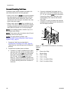
Connect Circulating Fluid Lines
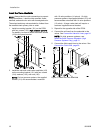
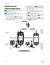
Circulation valves enable constant circulation of a
color when that color is not being sprayed:
•Whenacolorva
lve is closed, the system bypasses
the dosing pum
p by directing that color from the
inlet color v
alve to the outlet color valve to the
remote color
valve, through a circulation line, then
back to the co
lor supply.
• When a color v
alve is open, the circulation line is
shut off. Th
e color is directed through the material
A dosing pum
p and out to the remote color valve
stack and mi
x manifold, as in normal operation.
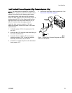
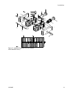
NOTE: On circulating systems, install a cap (T) on
any unused valve fittings.
NOTE: There can be only one solvent valve (S) and
one dump valve (D) per pump.
NOTE: On h
igh pressure systems, see
Install t
he Back Pressure Regulator (High Pressure
Systems O
nly), page 21.
1. Connect all fluid lines as described in
Connect Non-Circulating Fluid Lines, page 26.
These lines are used during normal mixing and
spraying.
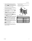
2. Connect the circulation lines as follows:
a. Connect a 1/4 npt(f) circulation line for each
color from the color valve’s circulation fitting
(R1, R2, etc.) on the inlet color valve stack
(B) to the corresponding circulation fitting
(R1, R2, etc.) on the outlet color valve
stack (C). This circulation line bypasses the
material A dosing pump when the color valve
is closed, allowing continuous circulation of
that color.
b. Connect a dedicated fluid supply line for
each color to the corresponding color valve
(C1, C2, etc.) on the outlet color valve stack.
Connect the other end of each line to the
corresponding color valve on the remote
color stack.
c. Connect a 1/4 n
pt(f) circulation line from the
circulation
port on each remote valve back to
thefluidsupp
ly container.
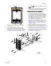
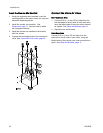
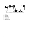
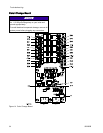
Figure 12 Valve Manifold Connections (Circulating
System)
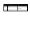
KEY
D
Dump valve fitting
S Solvent fitting
C1 Color 1
fitting
C2 Color 2 fitting
R1
Color 1 circulation fitting
R2
Colo
r 2 circulation fitting
28 333282B