


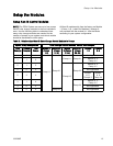
Setup the Module
s
Configure each module according to its designated
number, as follows:
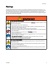
NOTICE
To avoid damaging the circuit boards, wear Part
No. 112190 grounding strap on your wrist and
ground appropriately.
To avoid elec
trical component damage, remove all
system power
before plugging any connectors.
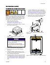
1. Remove elec
trical power from the system.
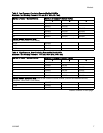
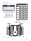
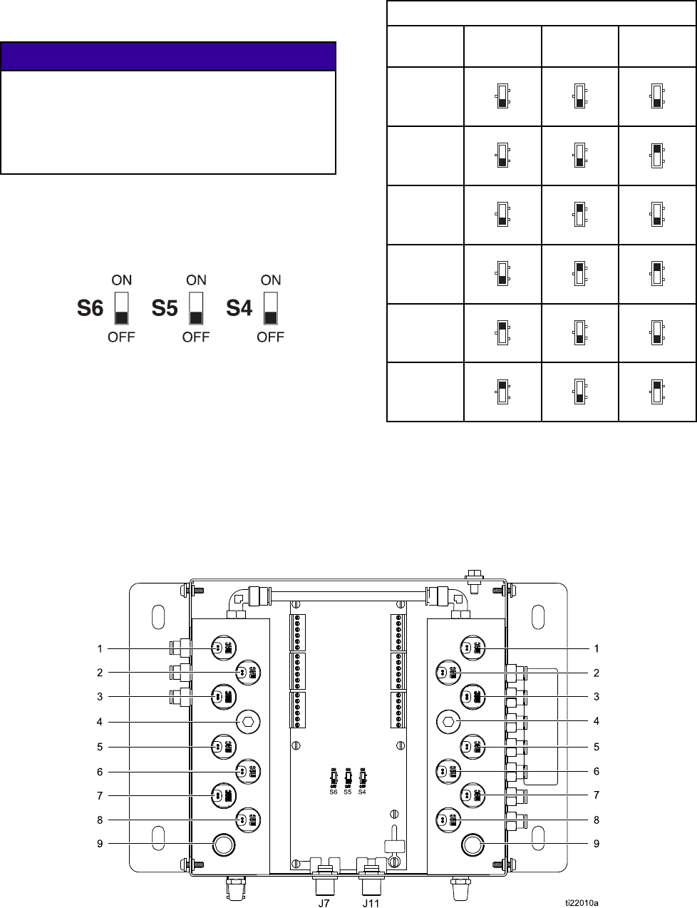
2. Open the col
or change module. Locate switches
S4, S5, and S
6onthecontrolmoduleboard.The
switches a
re shipped in the OFF position.
3. For each module, set the switches to ON or OFF,
as shown in the following table.
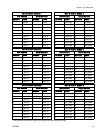
Non-IS Control Module Switch Settings
Control
Module
S6 S5 S4
Module 1
OFF
ON
OFF
ON
OFF
ON
Module 2
OFF
ON
OFF
ON
OFF
ON
Module 3
OFF
ON
OFF
ON
OFF
ON
Module 4
OFF
ON
OFF
ON
OFF
ON
Module 5
OFF
ON
OFF
ON
OFF
ON
Module 6
OFF
ON
OFF
ON
OFF
ON
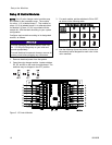
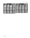
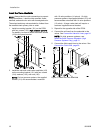
4. Use the following figure and tables to determine
the solenoid valve assigned to each valve in the
valve manifold.
NOTE: There can be only one solvent valve and one
dump valve per pump.
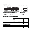
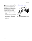
Inlet Manifold Outlet Manifold
Figure 1 Non-IS Control Module
1
4
333282B