Setup the Module
s
Setup the Modu
les
Setup Non-IS C
ontrol Modules
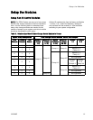
NOTE: The PD2K System can use up to four pumps
and six color change modules in the non-hazardous
area. Use the following table to understand how
many color change modules are needed for the
number of pumps in your system, and which module
should be associated to which pump.
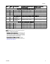
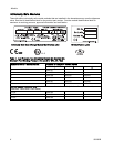
All Non-IS modules ship from the factory as Module
1 (Colors 1–8). Labels for Modules 2 through 6
are provided with the module kit. Affix the labels
according to your system configuration.
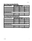
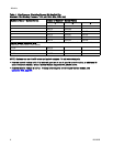
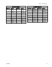
Table 5 . Relationship of Non-IS Color Change Control Modules to Pumps
System Pum
p Configuration
Color Chan
ge Control Modules, Colors, and Catalysts
Color
Pump(s)
Catalyst
Pump(s)
Total
Pumps
Module 1
(Colors
1–8)
Module 2
(Colors
9–16)
Module
3(Colors
17–24)
Module 4
(Colors
25–30)
Catalyst
1–2
Catalyst
3–4
1 0 1 Not Appli
cable
112
Pump # 1 Pump # 1
Module # 5
Pump # 2
213
Module # 5
Pump # 2
2 0 2 Not Applicable
224
Pump # 3
Modul
e
#5
Pump #
2
Modul
e
#6
Pump #
4
314
Module # 5
Pump # 2
303
Pump#1
Not A
pplicable
404
Pump#1
Pump#2
Pump #
3
Pump # 4
Not Applicable
333282B 13


