


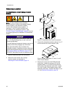
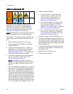

Installation
Connect the Fl
uid Lines
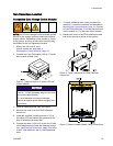
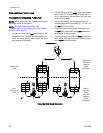
Connect Non-Circulating Fluid Lines
NOTE: There can be only one solvent valve (S) and
one dump valve (D) per pump.
NOTE: On high
pressure systems, see
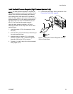
Install the
Back Pressure Regulator (High Pressure
Systems Onl
y), page 21.
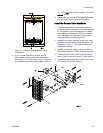
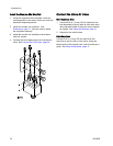
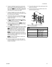
1. Use the top valve of the inlet valve stack as the
solvent valve (S). Connect a solvent supply line
to the 1/4 npt(m) solvent valve inlet on the color
and catalyst valve stacks.
2. Usethetopvalveoftheoutlet valve stack as the
dump valve (D). Connect a waste dump line to
the 1/4 npt(m) dump valve outlet on the color and
catalyst valve stacks.
3. Connect the supply line for each color to the
corresponding color valve fitting (C1, C2, etc.) on
the inlet color valve stack.
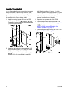
4. Connect a supply line from the bottom fitting of
the inlet color valve stack to the inlet manifold of
the material A dosing pump.
5. Connect a supply line from the outlet manifold of
the material A dosing pump to the bottom fitting
of the outlet color valve stack.
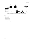
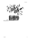
Hazardo
us
Area
Remote
Color an
d
Catalys
t
Valve
Manifol
ds
Non-
Hazardous
Area
Non-IS
inlet and
outlet
color and
catalyst
valve
manifolds
Valve Manifold Stack Schematic
26 333282B