


Installation
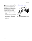
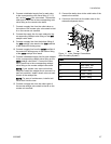
6. Connect a dedicated supply line for each color
to the corresponding color valve fitting (C1, C2,
etc.) on the outlet color valve stack. Connect the
other end of each line to the corresponding color
valvefittingontheremotecolorstack.
7. Connect a supply line from the outlet valve on
the bottom of the remote color valve stack to inlet
A on the remote mix manifold.
8. Connect the supply line for each catalyst to the
corresponding catalyst valve fitting on the inlet
catalyst valve stack.
9. Connect a supply line from the bottom fitting of
the inlet catalyst valve stack to the inlet manifold
of the material B dosing pump.
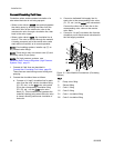
10. Connect a supply line from the outlet manifold of
the material B dosing pump to the bottom fitting
of the outlet catalyst valve stack.
11. Connect a dedicated supply line for each catalyst
to the corresponding catalyst valve fitting on the
outlet catalyst valve stack. Connect the other
end of each line to the corresponding catalyst
valve fitting on the remote catalyst valve stack.
NOTE: If your system uses more colors than
catalysts, branch the catalyst line to connect it to
each mix manifold. Install a check valve on each
branch of the catalyst line.
NOTE: For ease of maintenance, install a ball
valve at all fluid line tees.
12. Connect a supply line from the outlet valve of
the remote catalyst valve stack to inlet B on the
remote mix manifold.
13. Connect the static mixer to the outlet valve of the
remote mix manifold.
14. Connect a fluid line from the static mixer to the
automatic dispense device.
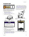
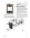
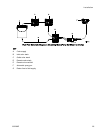
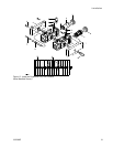
Figure 11
Color Change Connections
(Non-Cir
culating System)
KEY
A Air inlet
W
Seal wee
pand
lubrica
tion port
S Solvent fitting
C1 Color 1 fitting
C2 Color
2fitting
333282B
27