


Installation
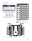
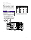
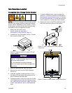
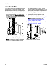
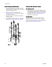
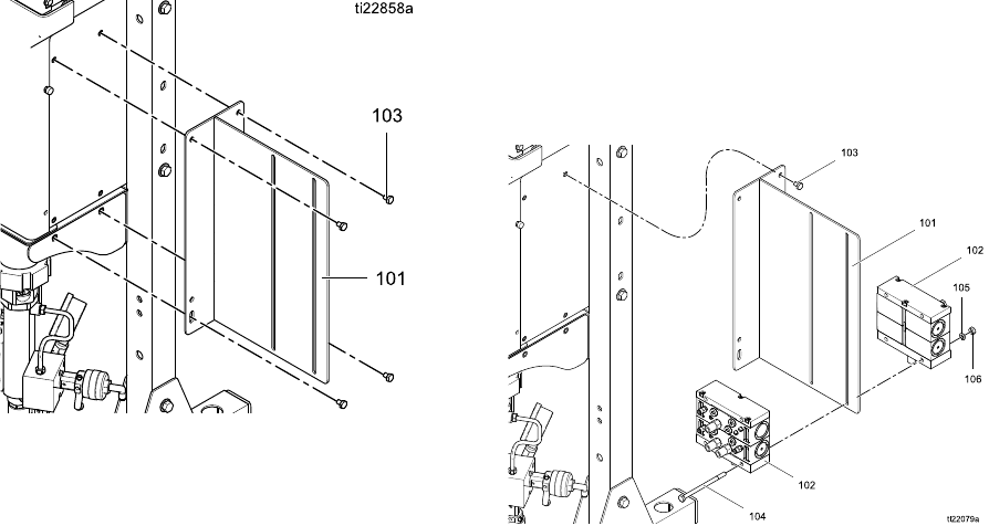
Install the Valve Manifolds
NOTE: Always label the color connections to prevent
cross-connections. Label the inlet manifold, outlet
manifold, and each color valve with its assigned color.
The solvent and dump valves should be furthest from
the manifold stack primary inlet or outlet.
1. Install a mou
nting bracket (101) on the PD2K
with four scr
ews (103). High pressure systems:
For stabilit
y, be sure to fasten the bottom screws
(103) to the
pump bracket.
2. Install the inlet and outlet valve manifolds (102)
on the mounting bracket (101) with four screws
(104), washers (105), and nuts (106).
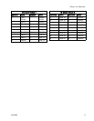
NOTE: On low pressure systems, the supplied
bracket (101) will accommodate a manifold
with 16 valve positions (14 colors). On high
pressure systems, the supplied bracket (101) will
accommodate a manifold with 14 valve positions
(12 colors). A larger valve stack will require a
customer supplied/sourced bracket.
3. Repeat for the opposite side of the PD2K.
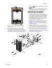
4. Connect the air lines from the solenoids to the
valves. See Connect the Valve Air Lines, page 24.
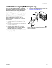
NOTE: On high pressure systems, see
Install the Back Pressure Regulator (High
Pressure Systems Only), page 21.
5. Connect the fluid supply lines to the valves. See
Connect the Fluid Lines, page 26.
Figure 6 Install the Valve Manifolds
20 333282B