


Installation
Installation
• To avoid electric shock, turn off power at
the main circuit breaker before opening the
enclosure.
• All electrical wiring must be done by a qualified
electrician and comply with all local codes and
regulations.
• Do not substitute or modify system components
as this may impair intrinsic safety.
• Do not install equipment approved only for
non-hazardous location in a hazardous location.
See the identification label for the intrinsic safety
rating for your model.
This equipment stays pressurized until pressure
is manually relieved. To help prevent serious
injury from pressurized fluid, such as skin injection,
splashing fluid and moving parts, follow the
Pressure Relief Procedure in the PD2K Operation
Manual before installing the kit.
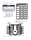
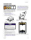
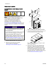
Mounting the Control Modules
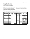
1. See Dimensions, page 71.
2. Ensure that the wall and mounting hardware
are strong enough to support the weight of the
equipment, fluid, hoses, and stress cause during
operation.
3. Using the equipment as a template, mark the
mounting holes on the wall at a convenient height
for the operator and so the equipment is easily
accessible for maintenance.
NOTE: The smaller color change control modules
must be mounted in the Non-IS area. The larger
remote color change module may be mounted
in the IS area.
4. Drill mounting holes in the wall. Install anchors
as needed.
5. Bolt the equipment securely.
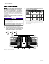
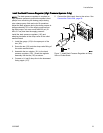
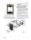
Air Supply
Connect a clean and dry air supply to the air inlet
fitting (317) of each color change control module in
the non-hazardous area and each remote module in
the hazardous area. The fitting is for 1/4 in. (6 mm)
ODtubing. Usea5micronfilter. Regulatetheair
pressure to 85–100 psi (0.6–0.7 MPa, 6.0–7.0 bar).
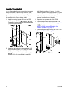
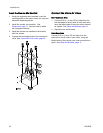
Grounding
This equipment must be grounded to reduce the
risk of static sparking and electric shock. Electric
or static sparking can cause fumes to ignite or
explode. Improper grounding can cause electric
shock. Grounding provides an escape wire for the
electric current.
Connect a ground wire from each color change
module in the non-hazardous area to a true earth
ground.
Intrinsically safe remote color change modules
located in the hazardous area must be connected to
a true earth ground in the hazardous area.
18 333282B