


Installation
Hazardous Location
Connect Remot
e Color Change Control
Module
NOTE: IS color change control modules
provide control for remote color/catalyst change
valves located in the hazardous location
for use with automatic spray systems. A
maximum of two IS control modules may
be installed in the hazardous location. See
IS Color Change Control Modules, page 66 for a list
of modules approved for installation in a hazardous
location.
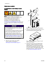
NOTICE
To avoid damaging the circuit boards, wear Part
No. 112190 grounding strap on your wrist and
ground appropriately.
To avoid electrical component damage, remove all
system power before plugging any connectors.
Only approved cables may be used in the
hazardous location. Hazardous location cables are
marked with a light blue flag next to each connector.
See Optional Cables and Modules, page 42 for a
list of M12 CAN cables for use in a hazardous area.
1. Remove electrical power from the system.
2. Mount the first remote color change
control module as described in
Mounting the Control Modules, page 18.
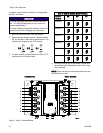
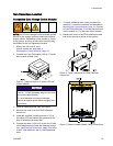
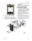
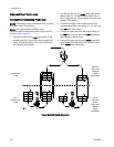
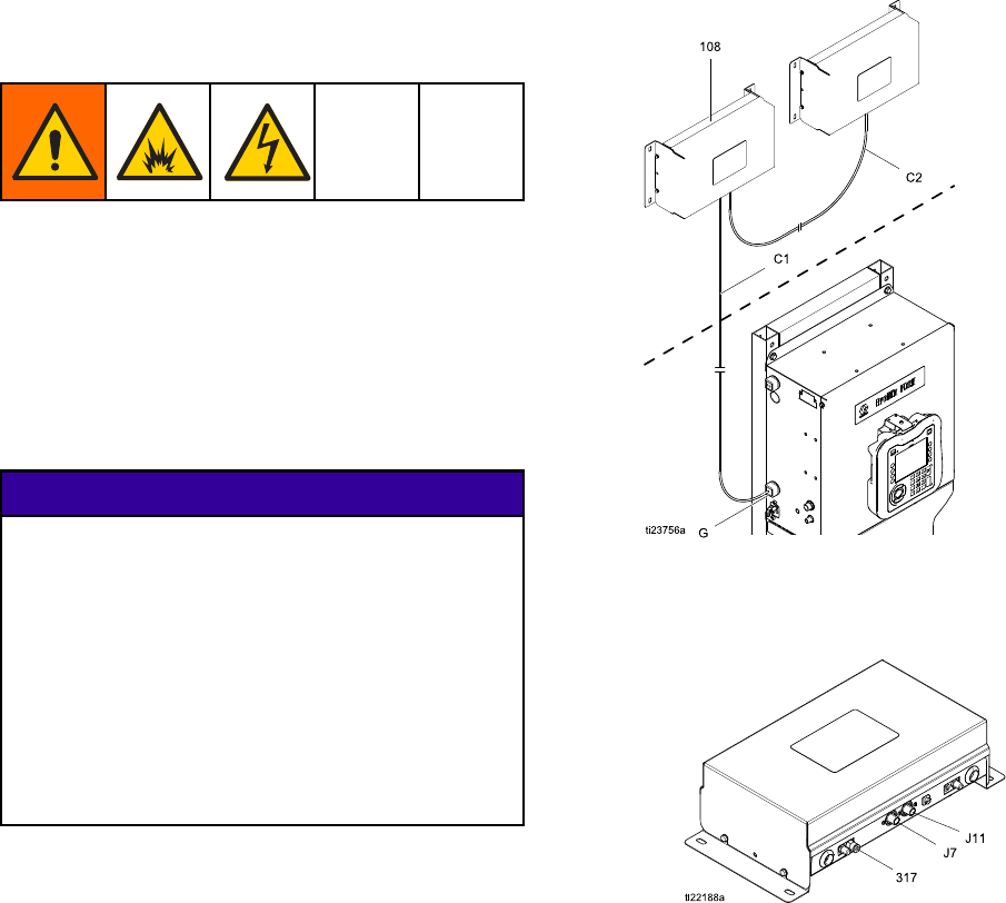
Figure 8 Intrinsically Safe Cable Connections
3. Connect the hazardous location cable (C1) to J7
on the remote color control module (108).
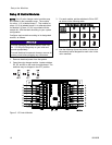
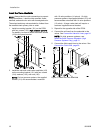
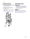
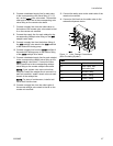
Figur
e 9 Cable Connectors J7 and J11 at IS
Color
Control Module
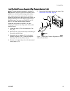
4. Remo
ve the cover from the PD2K electrical
cont
rol box. Install the grommet (G) on the
supp
lied cable (C1) and secure the grommet
to th
e side of the electrical control box. Locate
J4 on
theISsideoftheisolationboardinthe
ele
ctrical control box. Connect the cable (C1) to
J4.
See Electrical Schematics, page 36.
2
2
333282B