


Installation
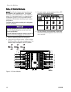
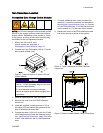
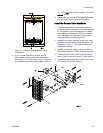
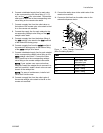
Figure 10 Detail of Isolation Board Cable
Connections
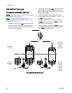
5. If your system includes a second remote
color control module mount it as described in
Mounting the Control Modules, page 18. Connect
the supplied hazardous location cable (C2) from
J11onthefirst color control module to J7 on the
second module.
6. Replace the cover of the PD2K electrical control
box before turning on power to the system.
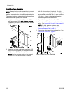
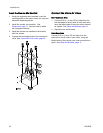
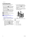
Install the Remote Valve Manifolds
1. Using the equipment as a template, mark the
mounting holes on the wall at a convenient height
for the operator and so the equipment is easily
accessible for maintenance. Mount the remote
valve manifolds near the remote color module
and the automatic dispensing device.
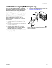
2. Install the mounting brackets for the color valve
manifolds and the catalyst valve manifolds. See
Dimensions, page 71. Use bolts to attach the
equipment securely.
3. Install the color and catalyst valve manifolds to
the brackets with four screws, washers, and nuts.
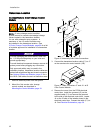
4. Connect the air lines from the solenoids to the
valves. See Connect the Valve Air Lines, page 24.
5. Connect the fluid supply lines to the valves. See
Connect the Fluid Lines, page 26.
333282B 23