


5-12 Series 90™-70 Enhanced Hot Standby CPU Redundancy User's Guide
–
May 2000 GFK-1527A
5
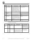
In the unlikely event that a rack failure does occur and is correctly diagnosed, the rack can be
replaced with power removed from the system. When the rack is replaced and power restored to the
system, the CPU will obtain synchronization with the active system and either take control or
become the backup CPU.
Central Processor Unit
If the redundancy CPU fails, the OK light on the CPU will turn off or blink. In addition, fault
information will be available in the Fault Table of one or both CPUs.
If the active CPU fails, control is transferred to the backup system. CPU replacement can be
accomplished by removing power from the rack and replacing the CPU. When power is returned to
the system, the program can be loaded into the CPU and the CPU started. It will then obtain
synchronization with the active system and either take control or become the backup CPU.
Redundancy Communications Module and Cables
If a fault is detected in a single Redundancy Communications Module or in its terminated I/O
cable, the backup RCM is used. Control does not transfer to the backup CPU. An RCM fault is
logged in the PLC Fault Tables of both PLCs.
The loss of an RCM is not fatal.
If there are
expansion racks within a system, and the cable fault is such that the system can no longer
communicate to the expansion racks, then the fault is fatal and the PLC is halted. Control then
transfers to the backup PLC.
If an RCM fault is detected, proceed as follows:
STOP the unit with the suspected bad RCM.
Turn power off at that rack.
Unplug the terminated cable from the RCM and replace the module.
Reconnect the terminated cable.
Power-up the rack with mode switch in STOP.
Verify that the REMOTE ACTIVE and REMOTE READY LEDs are on.
Note that the RCM
LEDs only update if the board is not faulted.
Switch the repaired unit to RUN.
Redundancy Communications Link Failures
There are two types of Redundancy Communications Link failures; a "Link Timeout" and a "Hard
Link Failure". When a
Link Timeou
t occurs, the RCM BOARD OK LED remains ON and the
LOCAL READY and LOCAL ACTIVE LEDs continue to reflect the status of the Local unit. The
REMOTE ACTIVE and REMOTE READY LEDs are not updated by the Remote unit until the
link is reinitialized by storing a configuration or power cycling either unit. When a
Hard Link
Failure
occurs, all five RCM LEDs go OFF. A power cycle of the Local unit is required to attempt
to reinitialize the failed link.