


1-6 Series 90™-70 Enhanced Hot Standby CPU Redundancy User's Guide
–
May 2000 GFK-1527A
1
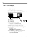
Genius I/O
The redundant portion of the system is based on Genius I/O. A system using standard Series 90-70
racks can have multiple Genius I/O bus networks. A system using the ½ slot redundant racks may
have only one bus in the CPU rack. Any Genius device can be placed on the bus (Genius blocks,
Field Control, Remote I/O Scanner, VersaMax I/O, etc.). The Genius devices are under control of
the active unit in the Redundancy system. The Genius Bus Controller in the Primary Unit has a
Serial Bus Address of 31; the Genius Bus Controller in the Secondary Unit has a Serial Bus
Address of 30. Data from Serial Bus Address 31 is the preferred data when data is being sent from
both units to devices on the Genius bus.
Local I/O
Local I/O can be included in the overall PLC system; however,
it is not
part of the Hot Standby
CPU Redundancy system. Control of Local I/O is done normally through the application program.
Transfer of this data between the redundancy CPUs is optional. A failure in the Local I/O system
will affect the system as described in GFK-0265, the
Series 90-70 Programmable Controller
Reference Manual
.
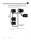
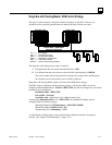
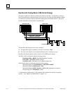
Cable Connections
In an Enhanced Hot Standby CPU Redundancy system that requires expansion racks, a Bus
Transmitter Module in rack 0 is connected by a parallel I/O cable to a Bus Receiver Module in the
next rack. The link is continued from this Bus Receiver Module to a Bus Receiver Module in the
next rack. This link is continued with a maximum of six expansion racks. The last Bus Receiver is
connected via an I/O cable with built-in termination (catalog number IC697CBL803 (3 feet (0.9m))
catalog IC697CBL811 (10 feet (3m)) or IC697CBL826 (25 feet (7.5m)). The last module in the
parallel I/O bus link must be a Redundancy Communications Module (RCM). This terminated I/O
cable allows replacement of the RCM without interrupting the running system. If no expansion
racks are used, the terminated I/O cable is connected directly from the Bus Transmitter Module to
the Redundancy Communications Module.