


GFK-1527A Chapter 1 Introduction 1-13
1
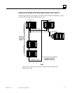
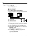
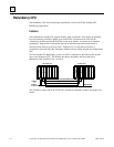
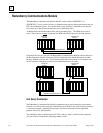
Duplex CPU Redundancy
Only discrete blocks (or Remote I/O Scanners with only discrete modules) can be
configured for Duplex CPU Redundancy mode. Blocks or I/O Scanners configured for
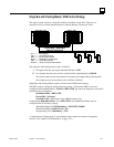
Duplex mode receive outputs from BOTH bus controllers 30 and 31, and compare them.
If devices 30 and 31 agree on an output state, the output goes to that state. If devices 30
and 31 send different states for an output, the block or I/O Scanner defaults that output
to its pre-selected Duplex Default State. For example:
Commanded State
from Device
Number 31
Commanded State
from Device
Number 30
Duplex Default
State in the Block
or I/O Scanner
Actual Output
State
On On Don’ Care On
Off On Off Off
Off Off Don’t Care Off
On Off On On
If either device 30 or 31 stops sending outputs to the block or I/O Scanner, outputs will be directly
controlled by the remaining device.
Online Programming
On-line changes to the application program are permitted in both the active unit and the backup
unit. The programming device must be connected to the system in which changes are to be made
in order to make any on-line changes. Note that all precautions regarding power source and
grounding for connecting the programming device must be followed in accordance with
instructions in the
Series 90-70 Programmable Controller Installation Manual
, GFK-0262.
A connection and disconnection of the parallel programmer cable should only be made with the
programmer properly grounded, and programming software properly booted up and in OFF-LINE
mode. For more information, refer to the
Series 90-70 Programmable Controller Installation
Manual
, GFK-0262.
On-Line Repair
An Enhanced Hot Standby CPU Redundancy system permits online repair of failed components
without disrupting the process under control. Control status of both the Primary and the Secondary
units can be monitored by the LEDs on the Redundancy Communications Module in each system.
When a component of the active unit fails, control switches to the backup unit. The failed
component can then be replaced after first removing power from the rack in which it is installed.
After replacement of the failed component and returning power to the rack, the backup unit
resynchronizes with the currently active unit. The unit that had failed, which was previously the
active unit, determines its role in the system based on configured control strategy.
Online repair is described in more detail in chapter 5.