


2-6 Series 90™-70 Enhanced Hot Standby CPU Redundancy User's Guide
–
May 2000 GFK-1527A
2
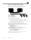
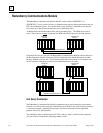
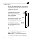
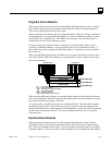
Redundancy Communications Module
The Redundancy Communications Module (RCM), catalog number IC697RCM711 or
IC687RCM711 (½ slot version), provides a communications path for sharing data between the two
CPUs in the redundant system. In a synchronized system, I/O data is controlled by one unit (the
active unit) but is shared between both units (active and backup units).
An RCM must be in both the Primary PLC and the Secondary PLC. The RCM must reside in
rack 0. There can be no empty slot between the RCM and the CPU (there can be other modules).
C B
T
M
R
C
M
31
Primar
y
Unit Secondar
y
Unit
30
P
S
P
S
B
T
M
R
C
M
Redundancy Communications Link
Redundanc
y
Communications Link
G
B
C
G
B
C
P
U
C
P
U
( RACK 0 )
( RACK 0 )
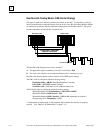
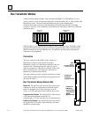
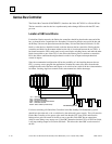
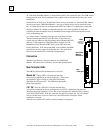
If the other PLC has only one rack, the Redundancy Communications Module connects directly to
the Bus Transmitter Module. If the other PLC has expansion racks, the RCM connects to a Bus
Receiver Module in the last rack. The termination plug at the end of the bus is not required since
the I/O cables for redundancy systems have termination built-in to the cables.
C B
T
M
R
C
M
31
Primar
y
Unit Secondar
y
Unit
30
P
S
P
S
B
T
M
R
C
M
Redundancy Communications Link
Redundancy Communications Link
G
B
C
G
B
C
P
U
C
P
U
( RACK 0 )
( RACK 0 )
P
S
B
R
M
P
S
B
R
M
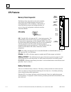
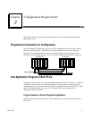
Unit Select Pushbutton
The Redundancy Communications Module's pushbutton can be used to manually switch control
from the
active
unit to the
backup
unit if the backup unit is
READY. T
he switch must be pressed for
1 second and released. Switching between units can also be controlled from the application
program with a SVC_REQ function.
The pushbutton status is checked by the PLC CPU software. After a switch has been requested,
you must wait 10 seconds before requesting another switch.