


3-4 Series 90™-70 Enhanced Hot Standby CPU Redundancy User's Guide
–
May 2000 GFK-1527A
3
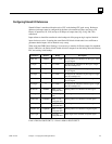
Finding the Memory Available for Application Program Storage
Shared I/O data is stored in the same memory as application program storage. To find the amount
of memory available for application program(s), subtract the overall transfer data amount from the
amount of memory (512K bytes for CGR772, 1024K bytes for CGR935) available for the
application program.
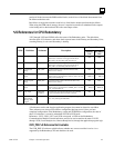
First, calculate the amounts of input and output data transferred:
Reference Type Reference Size If Point Faults are
Disabled
: If Point Faults are
Enabled
:
%I Bit (%I length x 4 ) ÷
8 (%I length x 5) ÷
8
%AI Word (%AI length x 2) (%AI length x 3)
%Q Bit
(%Q length x 4) ÷
8 (%Q length x 5) ÷
8
%M Bit (%M length x 4) ÷
8
%AQ Word (%AQ length x 2) (%AQ length x 3)
%R Word
(%R length x 2)
Then, add the input amount, the output amount, and an additional 8K bytes for synchronization
information:
total bytes of input data
(%I, %AI) transferred
+
total bytes of output data
(%Q, %AQ, %M, %R) transferred
+
8 Kbytes
for synchronization information
Last, subtract this amount from the total amount available for the application.
For example, if there are 10 Kbytes of input data transferred and 20 Kbytes of output data
transferred, then 10 Kbytes + 20 Kbytes + 8 Kbytes = 38 Kbytes needed for transferred data. This
is subtracted from the 1024 Kbytes of total memory on the CGR935:
1024K - 38K = 986 Kbytes available for the application program on the CGR935.
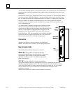
System Communications Window Considerations
The CGR772 and CGR935 model CPUs support the use of high-speed communications modules
such as the Ethernet Interface (Type 2). Requests from devices attached to these communications
modules are handled in the System Communications Window. Since these requests can be sent in
large volumes, there is the potential for the Systems Communications Window to be processing
requests for a significant amount of time. One way to reduce the risk of timing out the Redundancy
Communications Module/Bus Transmitter Module communications link between the CPUs is to
configure the System Communications Window for
LIMITED WINDOW
mode. This sets a
maximum time for the Systems Communications Window to run. Other options are to configure
the CPU sweep mode as
CONSTANT WINDOW
or
CONSTANT SWEEP
. The CPU will then cycle
through the communications and background windows for approximately the same amount of time
in both units.