


2-12 Series 90™-70 Enhanced Hot Standby CPU Redundancy User's Guide
–
May 2000 GFK-1527A
2
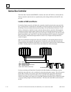
30. Data from Serial Bus Address 31 in the Primary PLC is the "preferred" data. The GDB control
strategy must be used and all redundant Genius outputs must be transferred from the active to the
backup unit.
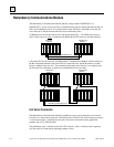
Each dual bus can have up to 30 additional Genius devices connected to it. One Serial Bus Address
must be reserved for a Hand-Held Monitor. Any type of Genius device can be connected to this
bus. A Genius I/O device will use outputs from Serial bus Address 31 in preference to data from
Serial bus Address 30. Outputs are determined by the Active Unit regardless of which bus
controller provides the outputs since all redundant Genius outputs must be transferred from the
active to the backup unit.
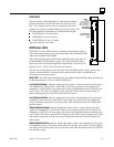
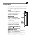
As a safety feature, a watchdog timer protects each Genius I/O link.
The bus controller periodically resets this timer. If the timer ever
expires, the bus controller stops functioning and its Channel OK LED
turns off. If this happens in a Dual Bus Genius network of a CPU
Redundant system, the paired GBC in the remote CPU drives the
Genius I/O blocks. If the remote unit GBC is not available, the BSMs
switch busses and use outputs from the other bus. The cause of the
failure must be remedied to re-establish communications.
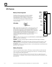
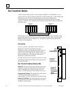
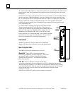
Connectors
The Bus Controller has a nine-pin connector for a Hand-Held
Monitor. Bus connections are made to a removable terminal board.
Bus Controller LEDs
The GBC has three LEDs; the bottom one is not used.
Module OK:
The top LED is
ON
when the board has
successfully completed the power-up diagnostics. If the power-
up diagnostics detect a failure or if the board fails during
operation, the LED goes
OFF
. The LED
blinks
during the
power-up diagnostics.
CH 1 OK
:
The CH 1 OK LED is
ON
after the board has
successfully completed the power-up diagnostics and
OFF
if a failure has been detected
during the power-up diagnostics or if its bus or bus controller fails while the CPU is running
(even in the STOP mode). If the bus controller fails the LED remains off. For a bus failure,
such as a broken wire or excessive bus errors, the LED remains off until the failure
condition is corrected.
The LED also remains
OFF
until its serial bus address is configured.
Hand-held
Monitor
Connector
Bus
Terminals
MODULE OK
CHANNEL 1 OK
LEDs
NOT USED