


GFK-1527A Chapter 2 System Components 2-9
2
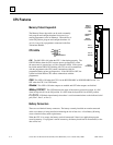
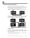
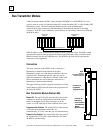
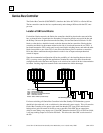
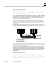
Bus Receiver Module
The Bus Receiver Module (BRM), catalog number IC697BEM711, is the expansion rack interface
to the I/O bus. The Bus Receiver Module connects to a Bus Transmitter Module in rack 0 or to a
Bus Receiver Module in the previous rack via a parallel I/O bus cable.
In a CPU Redundancy system with expansion racks, the last bus connection is to a Redundancy
Communications Module, as explained previously.
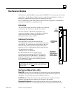
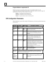
Connectors
The top connector on the Bus Receiver Module is for connection
to the previous Bus Transmitter or Bus Receiver Module.
The lower connector on the Bus Receiver Module is for
connection to the upper connector of a Bus Receiver Module in
the next expansion rack or to the upper connector of a
Redundancy Communications Module.
Cables and Termination
In an expansion I/O system, the cable between Bus
Transmitter/Receiver modules is an 18 twisted-pair cable with a
ground shield. The total maximum cable length from the CPU
rack to the most distant expansion rack (at the same ground
potential) is 50 feet. Standard parallel I/O bus cables that meet
this specification are available
in lengths of 5, 10, 25, and 50 feet.
In a non-redundant PLC system, this bus must be
terminated using terminator plug (IC697ACC702) on the
bottom connector of the last Bus Receiver. All BRMs are
shipped from the factory with a terminator plug installed.
For a redundant PLC system, these terminator plugs must
be removed from all BRMs.
In a Hot Standby CPU Redundancy system a special I/O cable with
built-in termination is used. Do not use the resistor plug with the
terminated cable.
Bus Receiver Module Status LEDs
Board OK
:
The top LED is
ON
when the CPU completes its power-up configuration of
the expansion rack and at least one module in that rack responds to the CPU requests for
information. It is
OFF
when any of these conditions are not met.
Last Rack
:
The middle LED is
ON
when the terminator plug is installed in the bottom
connector of this Bus Receiver Module and is
Off
when it is not installed.
Expansion Bus Active
:
The bottom LED
ON
indicates activity on the expansion bus in
the last 500 ms. Otherwise it is off and I/O modules in the rack are held in their default state.
LEDs
Connector to
Previous BTM
or BRM
Connector to
Redundancy
Communications
Module or Bus
Receiver Module
BOARD OK
LAST RACK
BUS ACTIVE