


GFK-1527A Chapter 2 System Components 2-11
2
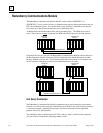
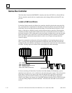
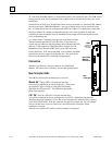
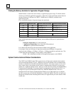
Single Bus Genius Networks
When using single-bus Genius networks in a Hot Standby CPU Redundancy system, one Genius
Bus Controller for the bus must be located in the Primary PLC and one in the Secondary PLC.
There can be multiple Genius busses in the system.
The bus controllers in the Primary PLC are assigned Serial Bus Address 31. The bus controllers in
the Secondary PLC are assigned Serial Bus Address 30. Data from Serial Bus Address 31 in the
Primary PLC is the "preferred" data. If the GHS Control Strategy is used, the Primary PLC is
normally the active unit in the redundancy system.
Each bus can have up to 30 Genius devices connected to it. One Serial Bus Address must be
reserved for a Hand-held Monitor. Any type of Genius device can be connected to the bus. A
Genius I/O device will use outputs from Serial Bus Address 31 in preference to data from Serial
Bus Address 30.
When using the GHS Control Strategy, the blocks receive outputs from the bus controllers in the
active unit. With the GHS Control Strategy, it is not necessary to transfer outputs from the active
unit to the backup unit.
C
P
U
C
P
U
B
T
M
R
C
M
G
B
C
Secondary Unit Primary Unit
31
P
S
P
S
B
T
M
R
C
M
G
B
C
30
G
B
C
30
G
B
C
G
B
C
31
G
B
C
31
30
Genius Bus
Genius Devices
Genius Devices
Genius Devices
Genius Bus
Genius Bus
When using the GDB control strategy, all redundant Genius outputs must be transferred from the
active to the backup unit. Therefore, outputs are determined by the active unit regardless of which
bus controller provides the outputs to the blocks.
As a safety feature, a watchdog timer protects each Genius I/O link. The Genius Bus Controller
periodically resets this timer. If this timer expires, the bus controller stops functioning and the
Channel OK LED turns off. If this happens in a CPU Redundancy system, the other bus controller
provides data to the Genius I/O blocks. The cause of the failure must be fixed to re-establish
communications.
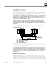
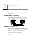
Dual Bus Genius Networks
When using dual bus Genius networks in a Hot Standby CPU Redundancy system, two Bus
Controllers for the bus pair must be located in the Primary PLC and two more in the Secondary
PLC. There can be multiple dual bus pairs. The bus controllers in the Primary PLC are assigned
Serial Bus Address 31. The bus controllers in the Secondary PLC are assigned Serial Bus Address
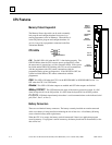
BTM..... Bus Transmitter Module
PS........ Power Supply
CPU...... Central Processor Unit.
BLOCK.. Genius I/O Block (or Field Control)
RCM..... Redundancy Communications Module
GBC...... Genius Bus Controller