


2-10 Series 90™-70 Enhanced Hot Standby CPU Redundancy User's Guide
–
May 2000 GFK-1527A
2
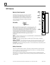
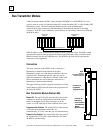
Genius Bus Controller
The Genius Bus Controller (IC697BEM731) interfaces the Series 90-70 PLC to a Genius I/O bus.
The bus controller scans bus devices asynchronously and exchanges I/O data with the CPU once
per scan.
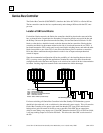
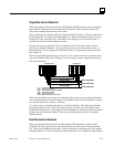
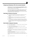
Location of GBCs and Blocks
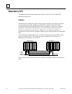
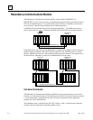
For dual bus Genius networks, the Genius bus controllers should be placed at the same end of the
bus, as pictured below. In particular, the Secondary Unit must be placed at one end of the bus and
the Primary Unit must be placed between the Secondary Unit and the Genius I/O blocks. No I/O
blocks or other devices should be located on the bus between the bus controllers. Placing the bus
controllers and blocks in this manner minimizes the risk of a bus break between the two CPUs. A
bus break between the CPUs could result in only some blocks switching busses, and make the other
blocks inaccessible to one of the CPUs. It also allows the Primary Unit to continue to control the
I/O in bus failure conditions that might otherwise result in loss of inputs and unsynchronized
control of outputs.
Since the recommended configuration still has the possibility of a bus breaking between the two
CPUs, you may want to program the application to monitor the status of the buses from the unit
configured at the end of the buses and request a role switch or bus switch if the bus is determined to
be broken. Locating single bus networks in the same manner has similar advantages.
C
P
U
C
P
U
B
T
M
R
C
M
G
B
C
30
Secondary Unit Primary Unit
31
B
L
O
C
K
B
L
O
C
K
P
S
P
S
B
T
M
R
C
M
G
B
C
B
L
O
C
K
30
G
B
C
G
B
C
31
Bus Switching Module
BTM..... Bus Transmitter Module
GBC.... . Genius Bus Controller
PS........ Power Supply..
CPU...... Central Processor Unit.
RCM...... Redundancy Communications Module
BLOCK.. Genius I/O Block
(
or Field Control
)
For fastest switching, all Genius Bus Controllers in the Hot Standby CPU Redundancy system
should be in the main rack, or in a rack driven by the main rack's power supply. This will cause the
Genius Bus Controller to lose power at the same time that the CPU loses power and allow the
backup unit to gain full control of the I/O as soon as possible. Each GBC has an output timer,
which it resets during every output scan. If the GBC determines that the CPU in its PLC has failed,
it will stop sending outputs to its Genius I/O block. This allows the other GBC to take control of
the I/O.