


GFK-1527A Chapter 2 System Components 2-7
2
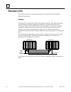
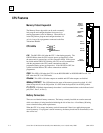
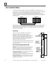
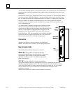
LEDs
Unit Select
Pushbutton
Connector
for
Communications
Cable
BOARD OK
LOCAL SYSTEM READY
LOCAL SYSTEM ACTIVE
REMOTE SYSTEM READY
REMOTE SYSTEM ACTIVE
Connector
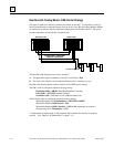
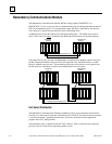
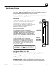
The top connector on the Redundancy Communications Module
must be connected via an I/O cable to the last rack of the
other
PLC. If no expansion rack is used, it is connected to the lower
connector on the Bus Transmitter Module of the other system. The
I/O cable with built-in termination is available in three lengths:
IC697CBL803, 3 feet (0.9 meters)
IC697CBL811, 10 feet (3 meters)
IC697CBL826, 25 feet (7.5 meters)
The lower connector is not used.
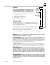
RCM Status LEDS
The RCM's five status LEDs are always updated by the appropriate system.
The module automatically turns off four of the LEDs (not the board OK LED)
if they are not updated within 500ms.
These LEDs report the status of the health of the RCM and control status of
the Hot Standby CPU Redundancy system. The status provided by these
LEDs can also be read from the application program logic in an area of %S
memory (%S33 - %S39). These status bits are read-only.
The term
Local System
below means the system where the RCM resides.
Remote System
is the
system to which the RCM is connected via the communications cable. Each RCM has an
associated local and remote system.
Board OK:
This LED lights when diagnostics are complete and the RCM has been determined to
be operating normally. It stays on unless the RCM fails.
Local System Ready
:
Indicates whether the local system is ready to become the active system
in a redundant PLC configuration. If this LED is on, the local system has been configured for
redundancy, is in RUN mode, and is able to take control of the redundant system if selected as the
active system. The local system MUST set the state of this LED at least once each sweep; if it
doesn't, the hardware forces the LED off after the timer expires.
Local System Active
:
Indicates whether the local system is the controlling (active) system in a
redundancy system. The local system MUST set the state of this LED at least once during each
sweep; if the local system fails to set the state of the LED, the hardware forces the LED off after
the timer expires.
Remote System Ready
:
Indicates whether the remote system is ready to become the active
system in a redundant PLC system. If the LED is on, the remote system has been configured for
redundancy, is in RUN mode, and is able to take control of the redundant system if selected as the
active system. The remote system MUST set the state of this LED at least once during each sweep;
if the remote system fails to set the state of the LED, the hardware forces the LED off after the
timer expires.
Remote System Active
:
Indicates whether the remote system is the controlling (active) system
in a redundancy scheme. The remote system MUST set the state of this LED at least once during
each sweep; if the remote system fails to set the state of the LED, the hardware forces the LED off
after the timer expires.