


Operation
Operation Instructions
3
3-19
A reset error will not occur for ion chambers calibrated in dose rate units (i.e. Brachytherapy chambers)
since the measurement is primarily concerned with amps or dose rate.
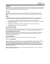
3.9.15 Reset Error (With Automatic Leakage Compensation Enabled)
The following discussion is only applicable when automatic leakage compensation is enabled and the ion
chamber is calibrated in Coulombs.
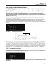
Holding the RESET/MEASURE button while on the Measurement screen causes the Model 35040
Therapy Dosimeter to reset the electrometer, zero all readings, and restart the measurement process.
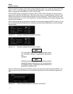
When an exposure is detected immediately following the reset that was not present prior to the reset, the
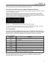
instrument displays the reset error message shown in Figure 3-31.
Figure 3-31. The Measurement screen showing the Reset Error message
To remove the error message, end the exposure and hold the RESET/MEASURE button. Wait a few
seconds for the instrument to complete the reset and repeat the exposure.
3.9.16 Annunciators
The top line of the display is dedicated to status annunciators. The Model 35040 Therapy Dosimeter
continuously monitors the ion chamber bias and battery voltages. If either one of these values is outside
the specified range, the Model 35040 displays an annunciator to indicate the error. Table 3-2 specifies
these annunciators and specifies the annunciators that may appear on the top line of the display.
Table 3-2. Annunciators
Annunciator Condition
??Bias
No bias measurement possible since the electrometer is not ready
ADC
Air density correction in use (only applicable to radiological
measurements)
ALC
Automatic leakage compensation enabled
LoBat
Low Battery voltage
LoBias
Low Bias voltage
HiBias
High Bias voltage
OvAmps
Overranged current
Rst
Resetting electrometer
Tmr
Timer in use
WAIT Bias Not Ready
The dosimeter is setting the bias
WAIT System Not Rdy
The dosimeter is resetting the electrometer (only applicable when
automatic leakage compensation is enabled)
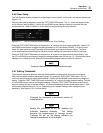
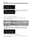
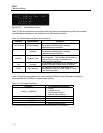
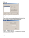
Figure 3-32 illustrates the locations of some annunciators. The battery, bias, and overranged current
annunciators appear at the same location, and the instrument alternates the displaying of each
annunciator when more than one is applicable.
and Repeat Exposure
Press RESET/MEASURE
ADC ALC
Internal Reset Error