


35040
Operators Manual
3-10
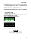
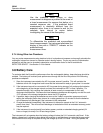
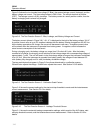
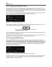
Figure 3-8 shows the ion chamber bias voltage (IC Bias), the system leakage current (Leakage), and the
battery voltage and current. The bias voltage shown is 300.0 volts. The central electrode is positive
(CEP). The leakage current is 0.001 picoamps. The battery current is a small positive number, thus the
battery is charging and is almost fully charged.
Figure 3-8. The Test Function Screen 2 - Bias, Leakage, and Battery Voltage and Current
The battery current (shown in Figure 3-8), “+0.1 A”, is displayed to the right of the battery voltage, “6.8 V”.
A positive current value of up to 2.5 amperes indicates that the battery is being charged from the AC line.
As the battery approaches full charge, the current will decrease to near zero. A negative current value
will be shown when the instrument is operated from battery power. A negative current indicates the
actual current consumption of the instrument.
During a charging cycle, the battery voltage can range from 5.5 volts to 8.5 volts. After the battery
reaches its full charge, the charging circuit switches to float charge stage with a corresponding voltage of
approximately 7 volts. The unit will remain in the float charge stage as long as the instrument is attached
to an AC line. When the instrument is operated from battery power, the voltage will read between 6.5
volts (battery fully charged) and 5.4 volts (low battery shutdown voltage).
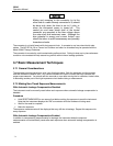
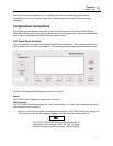
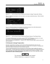
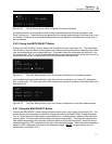
The two scale factors that appear in Figure 3-9 are those determined by a calibration agency.
QScaleFactor adjusts the charge. IScaleFactor adjusts the current. See Section 2.3 for details.
Figure 3-9. The Test Function Screen 3 - Calibration Scale Factors
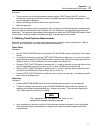
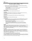
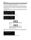
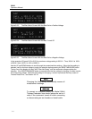
Figure 3-10 shows the present settings for the start and stop threshold currents and the instantaneous
current measurement. See Section 3.9.5 for details.
Figure 3-10. The Test Function Screen 4 - Leakage Threshold Screen
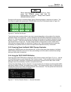
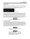
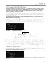
Figure 3-11 shows the automatic leakage compensation settings, which consist of the ALC status, start
and stop threshold currents, and the instantaneous current measurement. Refer to Section 3.9.5 for
details.
Leakage: 0.001 pA
ADC
IC Bias: 300.0 V CEP
Batt: 6.8 V +0.10 A
QScaleFactor=1.0000
IScaleFactor=1.0000
ADC
Start Thres: 1.0pA
Stop Thres: 0.9pA
Current: 0.0pA
ADC