


35040
Operators Manual
2-2
2.2.1 Power Supply
During operation, the instrument may be powered by line voltage in the range of 100 to 240 VAC or from
the internal 6 volt sealed lead acid battery for up to 8 hours. The power supply consists of a high
performance charger that continuously charges the battery whenever the instrument is plugged in. The
charger has three charging stages.
First stage: if the battery is fully discharged, the charger slowly recharges the battery until all cells in the
battery have a minimum charge level on them. The instrument will not operate until the battery has more
than the minimum charge on each cell. The first stage may be more than 18 hours depending on how
severely discharged the battery is.
Second stage: the charger enters a high charge rate that can restore more than 80% of the charge in 2 to
3 hours - even during normal operation. The battery voltage will range from 5.5 to 8.5 volts. The battery
current may be as high as 2.5 amps. After 3 hours of charging, the battery has enough charge for 8
hours of continuous operation.
Third stage: the charger enters a float charge stage that can be used indefinitely to maintain a full charge
on the battery without harm. The battery voltage is approximately 7 volts. The current will range from 0.5
to 0.01 amps. The lower the current, the closer the battery is to full capacity. For additional information
on care of the battery, see Section 3.8.
When operating from batteries, the battery current will be negative. The battery voltage will range from
6.5 volts to 5.4 volts. There are two automatic mechanisms to prevent excessive discharge of the battery.
If the voltage drops below 5.9 volts, a low battery annunciator (LoBat) is displayed on the front panel.
Less than 30 minutes of operating time are left. When the voltage drops to 5.4 volts, the firmware
automatically turns off the instrument. The hardware will turn off the power if the voltage drops below 5.4
volts.
The AC Power Line is fused as it enters the instrument with two fuses. These external fuses may be
replaced by the user (see Section 4.6 for details).
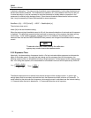
2.2.2 Front Panel
Pressing the power switch, an isolated, momentary-contact switch, once turns the power on. Pressing it
again turns the power off. At least 5 seconds should elapse after turning the power off to let the internal
parts reset before trying to turn power back on. The other keys, a matrix of 8 open contact membrane
switches, are scanned when any key closure is detected. The key code is stored until it is used. The four
line by twenty-character vacuum fluorescent display is easy to read over a wide range of lighting
conditions.
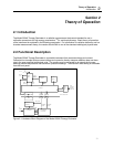
2.2.3 MicroController
A Motorola processor controls the instrument. The operating program is stored in EPROM. RAM is used
for volatile storage. Calibration parameters (gains and offsets) and customization parameters (ion
chamber calibration factors, pressure, and temperature units, bias settings) are stored in EEPROM. Each
time the instrument is turned off, all front panel settings are stored in a small portion of the EEPROM.
The settings are restored when the instrument is turned on.
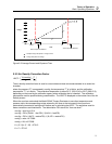
2.2.4 Serial Communications Port
The serial port is configured as an RS-232C data communications device (DCE) running at 9600 baud, 8
bits, no parity, and 1 stop bit. The protocol uses XON/XOFF handshaking. This port is used for factory
calibration and testing, for calibration, for customization, and for remote control/data acquisition.
Inadvertent changes of the calibration or customization parameters are prevented by use of a three-step
sequence.