


Operation
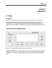
Operation Instructions
3
3-9
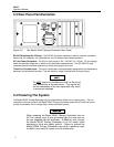
When attempting to turn the instrument on, firmly
press the POWER button and hold for
approximately one second. Always allow several
seconds between retries.
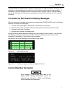
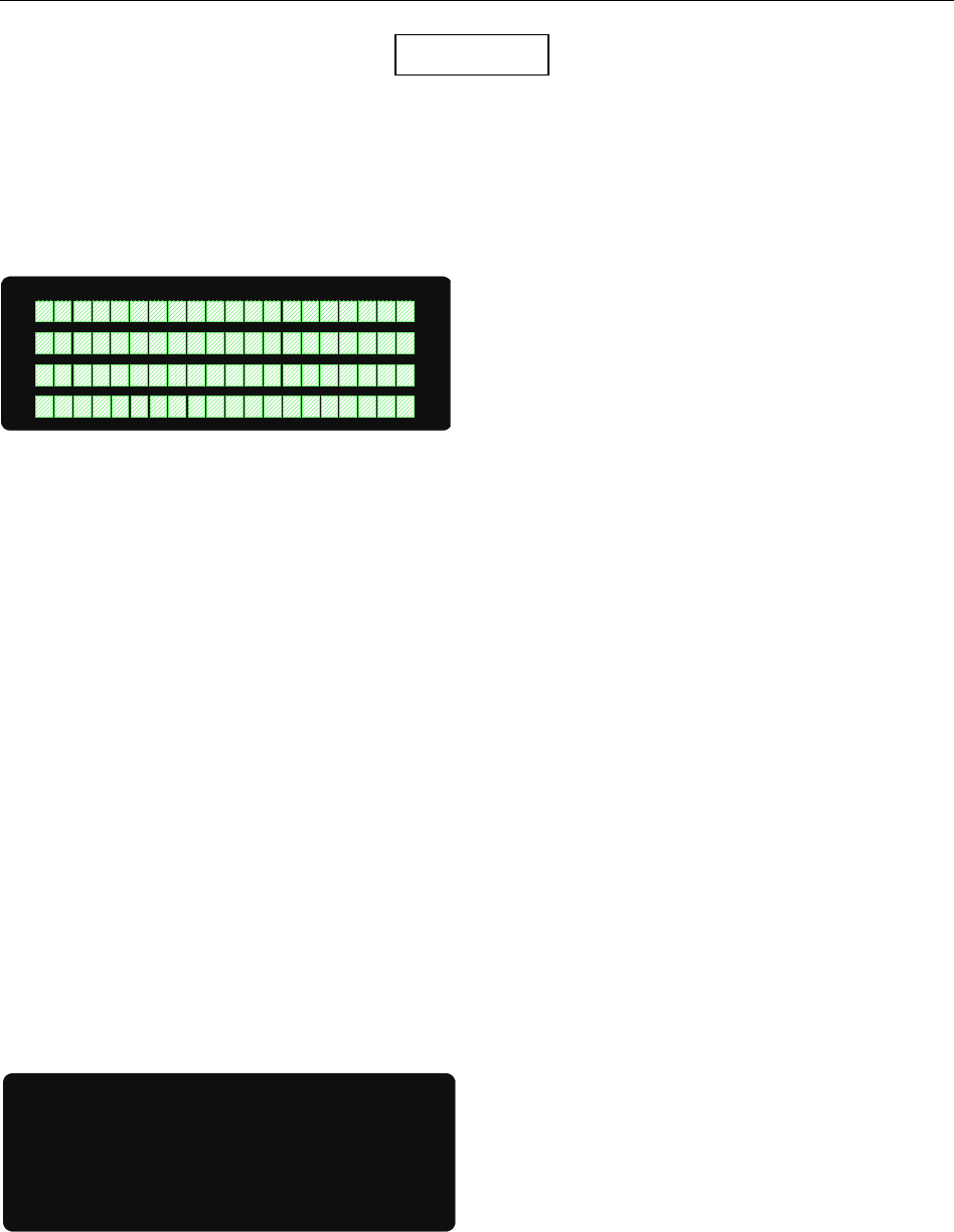
During this self-test period, the Model 35040 Therapy Dosimeter displays a sequence of screens. The
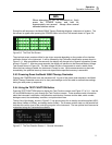
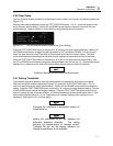
first screen to appear after pressing the POWER button is the Pixel Test screen shown in Figure 3-6.
Figure 3-6. The Pixel Test Screen
The pixel test screen remains visible for two to ten seconds depending on the number of ion chamber
calibration factors in the instrument. It will be followed by the Calibration Identification screen shown in
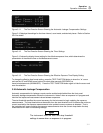
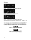
Figure 3-11. After an additional two seconds, the display will change to the General Information Screen
shown in Figure 3-7. After two more seconds, the display will advance to the Bias and Battery Voltage
Test Screen shown in Figure 3-8. The bias voltage will take a few seconds to reach a stable value.
When the bias voltage is stable, the instrument is ready for use. While measurements may be made
immediately, the specified warm up time must elapse before specified accuracy is warranted.
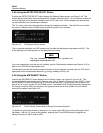
3.9.3 Powering Down the Model 35040 Therapy Dosimeter
Pressing the POWER button turns the instrument off. As part of the power down sequence, the Model
35040 Therapy Dosimeter saves all of its front panel settings and is thus able to restore these settings
during the next power up sequence.
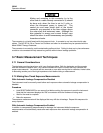
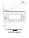
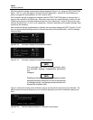
3.9.4 Using the TEST FUNCTION Button
Press the TEST FUNCTION button to display the Test Function screens, see Figure 3-7 to 3-11. Use the
UP and DOWN buttons to cycle through the Test Function screens. These screens contain information
about the instrument’s calibration, the calibration scale factors, firmware revision date, serial number,
leakage current, bias and battery condition, and optional text lines.
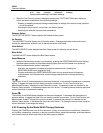
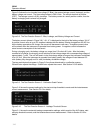
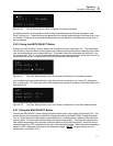
The top line of the display, shown in Figure 3-7, has annunciators for air density correction applied (ADC),
bias status (LoBias or HiBias), and battery status (LoBat). The firmware revision date, on the second line,
indicates the revision level of the controlling program in the instrument. The two optional text lines can be
customized using the Customization software.
Figure 3-7. The Test Function Screen 1 - General Information
NOTE
*Optional Text Line2
*Optional Text Line1
ADC
FW Rev: 10JUN93 A