


Daniel 3812 Liquid Ultrasonic Flow Meter Installation Manual Section 3: Electrical installation
3-9000-765 Rev H May 2015
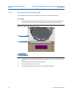
Clamped band shroud security seals 67
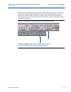
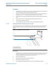
Procedure
1. Beneath the meter, install the security wires into and through the left front bolt (Item B)
and feed through the holes in the right back bolt (Item D).
2. Repeat wire installation through the right front bolt (Item E) to the left rear bolt (Item C)
as
shown in Figure 3-12. The maximum wire diameter .078 inch; 2.0 mm.
3. Position the wire to prevent counterclockwise ro
tation of the bolts when the seal wire is
taut.
4. Adjust the security wire, removing all slack and thread into the lead seal.
5. Cut wire ends to remove excess wire.
6. This completes the bolted band shroud
s
ecurity seal installation procedure.
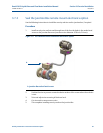
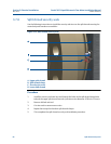
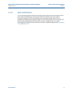
3.7.5 Clamped band shroud security seals
Use the following instructions to install the security seal wires, if required, on the two top end
shrouds covering the worm screw clamps. This procedure applies to clamped band shroud
meters.
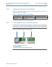
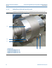
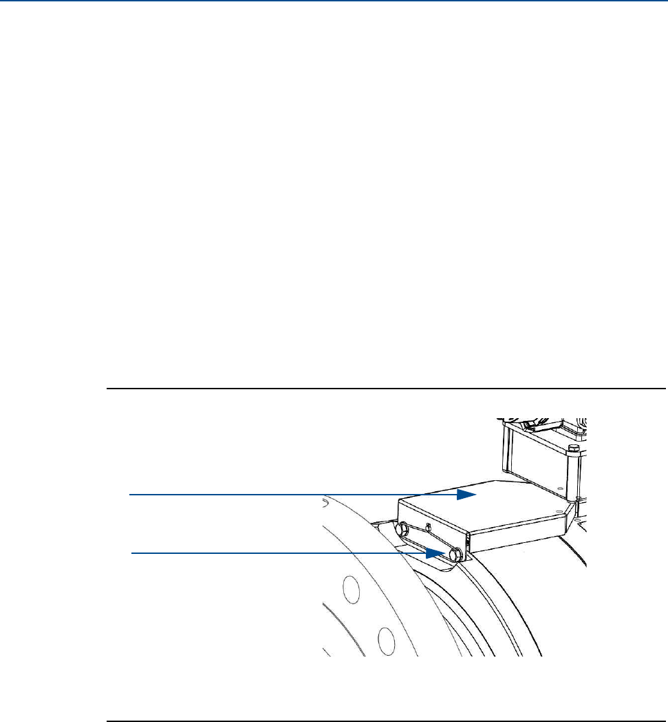
Figure 3-13 Clamped shroud security seals
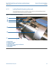
Procedure
1. Install the security seal wire into and through the two bolt holes on the top end shrouds
(maximum wire diameter .078 inch; 2.0 mm). Position the wire to prevent counter-
clockwise rotation of the screws when the seal wire is taut.
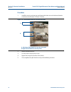
2. Remove all slack and seal.
3. Repeat previous step for the other top end shroud.
4. Cut wire ends to remove excess wire.
5. This completes the clamped band shroud security seal installation procedure.
A.
A. Top end shroud
B. Security wire seals
B.