


Daniel 3812 Liquid Ultrasonic Flow Meter Installation Manual Section 3: Electrical installation
3-9000-765 Rev H May 2015
CPU Module labeling and LED indicators 51
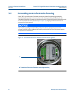
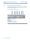
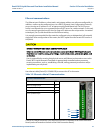
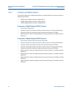
3.5.1 CPU Module labeling and LED indicators
The meter’s metrology mode and the status of the data transfer from the Acquisition Module to
the CPU Module is indicated via light-emitting diode (LED) status indicators. The Write PROT.
switch protects the meter’s configuration,
Figure 3-3 CPU Module labeling and LED indicator
s
A.
B.
C.
D.
E.
A. Acquisition/Measurement mode
B. Power
C. RX (RS-485/RS-232) - receiving data
D. LED 4 - not used
E. LED 5 - not used
F. TX (RS-485/RS-232) - transmitting data
F.
G.
G. Link (Eth1 Link) - user Ethernet connection